1.Introduction
Le step-up transformer is a core electrical device used in power transmission, industrial systems, renewable energy, and even household applications. Its main function is to increase voltage from a low level to a higher level, ensuring efficient long-distance transmission and compatibility with high-voltage equipment.
This article covers everything from working principle, voltage ratio formula, types, applications, advantages, selection tips, maintenance, to FAQs — making it a complete guide for engineers, technicians, and enthusiasts alike.
Are you looking for a specific high-voltage solution for your industrial project?
👉Get a Free Technical Consultation & Quote Now
Table of Contents (TOC)
- Introduction
- What Is a Step Up Transformer?
- How a Step Up Transformer Works
- Step Up vs Step Down Transformer
- Construction & Key Components
- Types of Step Up Transformers
- Applications of Step Up Transformers
- Advantages of Step Up Transformers
- Selection Guide
- Safety & Maintenance
- FAQ
2.What Is a Step Up Transformer?
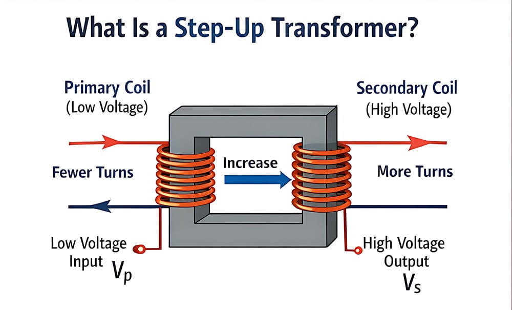
UN step-up transformer is an electrical device designed to raise (or “step up”) the voltage from a low level to a higher level in alternating current (AC) systems. It operates on the fundamental concept of electromagnetic induction and is widely used in power generation, distribution, and industrial electrical systems.
In simple terms:
Step up transformers take low voltage input and output high voltage, while maintaining power (minus losses).
This is especially critical in long‑distance power transmission where transmitting at high voltage minimizes energy losses.
3.How a Step Up Transformer Works
Electromagnetic Induction
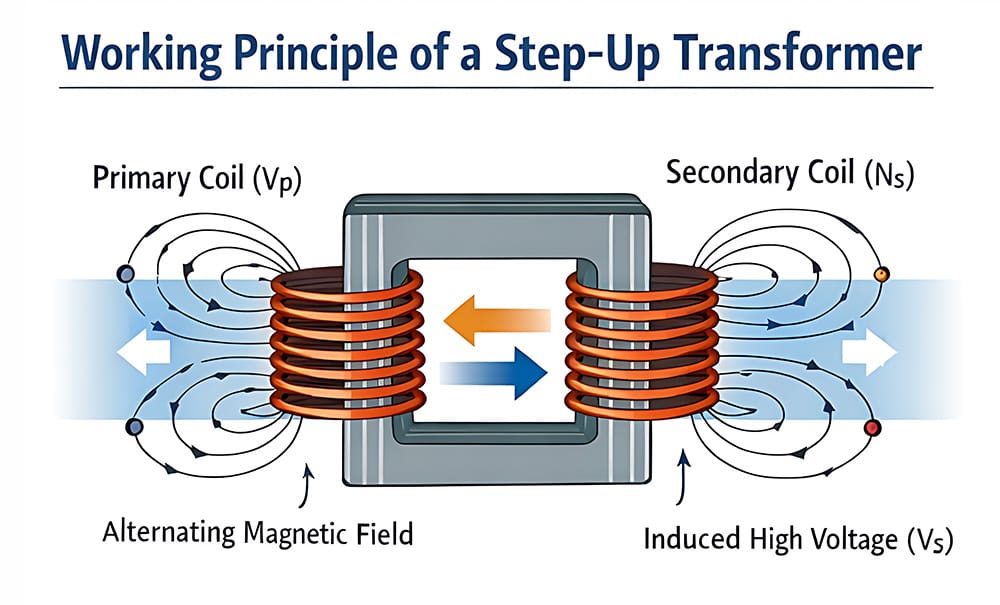
The working principle of a step-up transformer is based on Faraday’s Law of Electromagnetic Induction. When an alternating current (AC) flows through the primary winding (or coil), it creates a changing magnetic field. This magnetic field passes through the transformer’s iron core and induces a voltage in the secondary winding. The magnitude of that induced voltage depends on the ratio of turns in the windings.
Voltage Ratio Formula
The core formula that defines the relationship between voltages and the number of winding turns is:
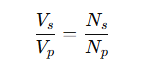
- Vs: Secondary voltage
- Vp: Primary voltage
- Ns: Number of secondary turns
- Np: Number of primary turns
In a step up transformer:
Ns > Np ⇒ Vs> Vp
This means the transformer increases voltage while decreasing current proportionally — an inverse relationship as required by conservation of energy (minus efficiency losses).
Efficiency and Losses
Even high-efficiency transformers experience minor losses:
| Loss Type | Cause | Effect |
|---|---|---|
| Copper Loss | Resistance in windings | Heat generation |
| Iron Loss | Hysteresis & eddy currents | Slight efficiency reduction |
| Leakage Flux | Imperfect magnetic coupling | Minor voltage drop |
Typical efficiency: 95–99%.
Selecting the wrong KVA rating can lead to overheating and system failure. Use our professional sizing tool to ensure your step-up transformer matches your load demand perfectly.
👉Try Our Free KVA Capacity Calculator
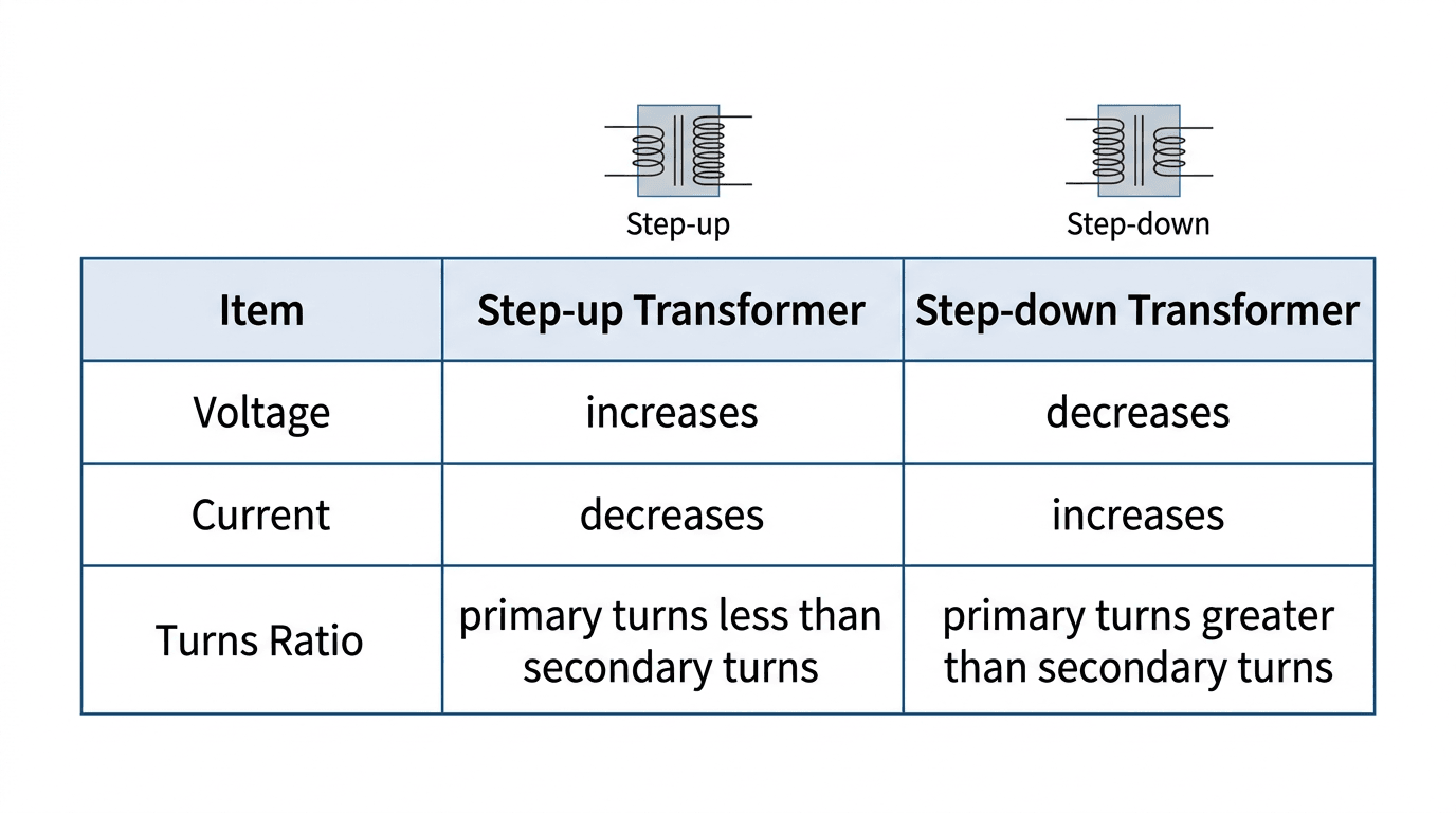
4.Step Up vs Step Down Transformer
1.Step-Up Transformer
UN step-up transformer increases the voltage from the primary winding to the secondary winding.
- Turns Ratio: The number of turns in the secondary winding is greater than the primary ($N_s > N_p$).
- Voltage Output: The output voltage is higher than the input voltage ($V_s > V_p$).
- Current Behavior: According to the Law of Conservation of Energy, as voltage increases, the current must decrease ($I_s < I_p$).
- Key Applications:
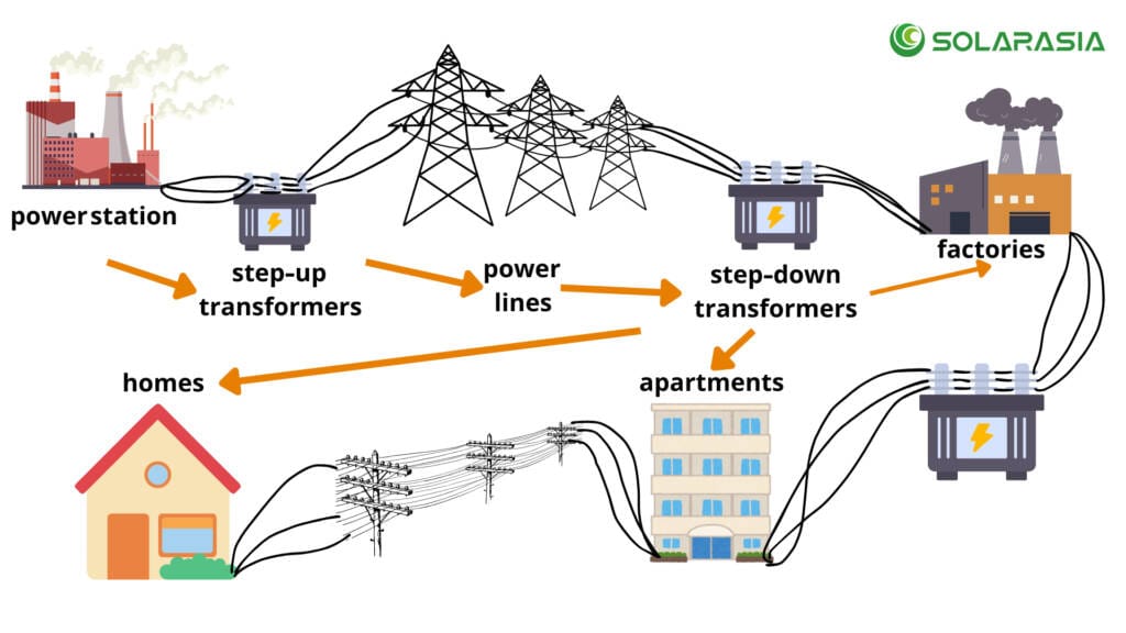
- Power Power Plants: Used to “step up” generated electricity to extremely high voltages (e.g., 220kV to 765kV) for long-distance transmission.
- Efficiency: Higher voltage allows for lower current, which significantly reduces energy loss due to resistance in transmission lines ($P_{loss} = I^2R$).
- Electronic Devices: Used in CRT monitors, X-ray machines, and microwave ovens that require high operating voltages.
2.Step-Down Transformer
A step-down transformer decreases the voltage from the primary winding to the secondary winding.
- Turns Ratio: The number of turns in the primary winding is greater than the secondary ($N_p > N_s$).
- Voltage Output: The output voltage is lower than the input voltage ($V_s < V_p$).
- Current Behavior: As the voltage drops, the current increases ($I_s > I_p$), making it suitable for high-current applications.
- Key Applications:
- Local Distribution: Found in neighborhood transformer drums that convert high-voltage grid power down to 110V/220V for household use.
- Consumer Electronics: Power adapters for laptops and phones step down 220V AC to low-voltage DC (5V, 12V, 19V).
- Welding: Electric welders require very high current at low voltage to melt metal safely.
3.Comparison Summary Table
| Fonctionnalité | Step Up | Step Down |
|---|---|---|
| Voltage Output | Higher | Lower |
| Current Output | Lower | Higher |
| Turns Ratio | Secondary > Primary | Secondary < Primary |
| Common Use | Power transmission | Distribution / consumer use |
| System Type | Industrial & grid | Household / low voltage |
5.Construction & Key Components
While the theory of a step-up transformer is simple, its physical construction is an engineering marvel designed to handle high voltages and minimize energy loss. Here are the five critical pillars of its architecture:
1. The Magnetic Core (The Flux Path)
The core is the “highway” for magnetic flux. It is not a solid block of metal; rather, it is made of thinly sliced laminations of High-Grade Silicon Steel.
- Why Laminated? To break up “Eddy Currents”—internal loops of electricity that cause massive heat loss.
- Why Silicon Steel? It has high magnetic permeability, meaning it can be magnetized and demagnetized easily with minimal energy loss (Hysteresis loss).
2. Primary Winding (The Input Gate)
In a step-up transformer, the primary winding is connected to the low-voltage AC source.
- Design Fact: Since $P = V \times I$, at a lower voltage, the current ($I$) is significantly higher.
- Construction: To handle this high current without melting, the primary winding typically uses thicker copper or aluminum wire compared to the secondary.
3. Secondary Winding (The High-Voltage Output)
This is where the magic happens. The secondary winding has a much higher number of turns ($N_s > N_p$).
- Design Fact: Because the voltage is stepped up, the current is lower.
- Construction: The wire used is often thinner than the primary wire, but it requires much more robust space and wrapping to handle the increased electrical pressure (voltage).
4. Insulation System (The Safety Barrier)
Insulation is the most critical factor for the lifespan of a step-up transformer. As voltage increases, the risk of “arcing” (electricity jumping through the air) rises.
- Internal Insulation: Coils are coated with specialized synthetic resins or enamel.
- Inter-layer Insulation: Sheets of cellulose-based paper or Nomex are placed between winding layers to prevent internal short circuits.
5. Cooling & Enclosure (The Thermal Management)
Stepping up voltage generates significant heat. Without a cooling system, the insulation would degrade and fail.
- Dry-Type Transformers: Use natural or forced air (fans) for cooling. These are common for indoor applications or smaller step-up units.
- Oil-Immersed Transformers: The core and coils are submerged in Naphthenic Mineral Oil. The oil serves a dual purpose: it is a superior insulator and it carries heat away from the core to external radiators through convection.
6.Types of Step Up Transformers
Not all step-up transformers are built the same. Depending on the voltage levels and the environment, they are categorized into four primary types:
1. Power Transformers (The Grid Giants)
These are the massive units you see at power plants and transmission substations. They are designed to operate at 100% efficiency (or as close as possible) during peak loads.
- Scale: Typically rated in Megavolt-Amperes (MVA).
- Purpose: They “step up” generated voltage (usually 11kV to 25kV) to extra-high voltages like 220kV, 400kV, or even 765kV for long-distance travel.
- Key Feature: They are almost always oil-immersed for superior cooling and insulation over decades of service.
2. Industrial Transformers (The Factory Workhorses)
In industrial settings, certain machinery requires a higher voltage than what the standard local grid provides.
- Purpose: To power heavy-duty equipment like large motors, industrial furnaces, and specialized manufacturing lines.
- Application: If a factory receives 480V but a specific imported CNC machine or hydraulic press requires 600V, an industrial step-up transformer bridges that gap.
- Key Feature: Built with high ruggedness to withstand vibrations and dust in a factory environment.
3. Portable / Home Use Transformers (Travel & Appliance Converters)
These are compact, user-friendly devices often used by travelers or people moving between countries with different voltage standards.
- Example: Stepping up 110V/120V (common in the US/Canada) to 220V/240V (common in Europe/Asia).
- Purpose: To run high-end kitchen appliances, hair dryers, or audio equipment safely without frying the internal circuitry.
- Key Feature: Often called “Plug-and-Play” converters; they usually include built-in fuse protection and universal sockets.
4. Three-Phase Transformers (The Backbone of Modern Energy)
While single-phase is fine for homes, the industrial world and the “Green Energy” sector run on three-phase power.
- Renewable Energy: Used in Wind Farms and Solar Parks to step up the variable AC power generated by turbines/inverters before feeding it into the national grid.
- Efficiency: They are more material-efficient than using three separate single-phase transformers.
- Key Feature: Features three sets of primary and secondary windings (usually configured in Delta or Wye patterns) to ensure a balanced and continuous power flow.
Comparison at a Glance
| Taper | Capacity | Primary Use | Méthode de refroidissement |
| Power | Very High (MVA) | Transmission Grids | Oil-Cooled |
| Industrial | Medium to High | Factories / Heavy Machinery | Air or Oil-Cooled |
| Portable | Low (Watts) | Home Appliances / Travel | Natural Air (Dry) |
| Three-Phase | Haut | Renewable Energy / Utilities | Oil-Cooled / Forced Air |
7.Applications of Step Up Transformers
Key Applications
- Power Transmission: Reduces energy loss over long distances
- Industrial Equipment: Motors, induction heaters, heavy machinery
- Renewable Energy: Solar PV systems, wind turbines
- Home Appliances: Adapting voltage standards
- Audio & Specialty Uses: Boosting low-voltage signals
Example Table: Renewable Energy Use
| Source | Tension d'entrée | Tension de sortie | Purpose |
|---|---|---|---|
| Solar PV | 600V | 11kV | Grid connection |
| Wind Turbine | 690V | 33kV | Long-distance transmission |
8.Advantages of Step Up Transformers
Step-up transformers are the unsung heroes of modern electrification. Without them, our current power grid would be physically impossible and economically ruinous. Here are the primary benefits:
1. Drastic Improvement in Transmission Efficiency
The most significant advantage is the reduction of energy waste. When electricity travels through miles of wire, it encounters resistance, which turns electrical energy into wasted heat ($P_{loss} = I^2R$).
- The Math of Savings: By stepping up the voltage, the current ($I$) is proportionally decreased. Since the power loss is proportional to the square of the current, doubling the voltage can reduce energy losses by a factor of four.
- Economic Impact: This efficiency allows power plants to be located hundreds of miles away from cities (near fuel sources or dams) without losing a massive percentage of the generated power along the way.
2. Adaptation to Global Voltage Standards
In a globalized economy, equipment is often manufactured to different electrical standards (e.g., 110V in the US vs. 220V in China/Europe).
- Seamless Compatibility: Step-up transformers act as a “universal translator” for power. They allow high-end medical, industrial, or specialized consumer equipment to function perfectly in regions where the native grid voltage is too low.
- Versatility: They enable businesses to import or export machinery without needing to redesign the internal electrical components of the machines.
3. Supporting High-Voltage Industrial Demands
Heavy industry requires a level of “torque” and power that standard residential lines cannot provide.
- Heavy-Duty Power: Many industrial processes, such as Electric Arc Furnaces (EAF) for steel making or large-scale Electrolysis for aluminum production, require massive voltage levels to initiate and maintain the process.
- Equipment Longevity: Providing the correct high voltage ensures that industrial motors run at their designed efficiency, preventing overheating and premature mechanical failure caused by “voltage sag.”
4. Ensures Stable and Continuous Power Delivery
Step-up transformers play a key role in regulating the “pressure” of the electrical grid.
- Voltage Regulation: They help maintain a consistent voltage level across the grid, compensating for the natural voltage drops that occur as electricity travels further from the source.
- Grid Resilience: In renewable energy farms (Solar and Wind), step-up transformers are essential for stabilizing the fluctuating output of inverters and turbines, ensuring the energy is “grid-ready” before it is injected into the main lines.
5. Cost-Effective Infrastructure
While a transformer is a capital investment, it actually saves money on infrastructure.
- Thinner Cables: Because stepping up the voltage reduces the current, utility companies can use thinner copper or aluminum cables for long-distance lines.
- Reduced Material Costs: This saves thousands of tons of expensive conductive metal and reduces the weight load on transmission towers.
9.Selection Guide
- Voltage Ratings: Input & output match
- Rated Capacity (kVA): Match load demand
- Frequency: 50 Hz / 60 Hz compatibility
- Cooling Method: Dry vs oil-immersed
- Safety Certifications: CE, UL, IEC
10.Safety & Maintenance
UN step-up transformer is a significant investment. Proper maintenance not only prevents catastrophic failures but also ensures compliance with international safety standards (such as IEEE or IEC). Following a strict Preventative Maintenance (PM) schedule is essential for operational safety.
1. Avoid Overloading (Load Management)
Operating a transformer beyond its rated KVA (Kilovolt-Amperes) capacity is the leading cause of premature failure.
- The Risk: Overloading causes the internal windings to overheat, which rapidly degrades the insulation. Once the insulation becomes brittle, a short circuit is inevitable.
- SEO Tip: Always monitor the Peak Load and ensure the transformer has a safety margin (typically 20%) to handle unexpected surges.
2. Ensure Proper Grounding (Earthing)
Correct grounding is the most critical safety feature for protecting both the equipment and the personnel working near high-voltage installations.
- System Integrity: A robust grounding system provides a low-resistance path for fault currents. This prevents the transformer casing from becoming “live” during a dynamic fault.
- Neutral Grounding: Ensure that the neutral point is properly grounded to stabilize the voltage phases and prevent floating voltages that could damage connected machinery.
3. Maintain Optimal Ventilation & Thermal Management
Heat is the silent killer of electrical components. A step-up transformer naturally generates heat during the voltage conversion process.
- For Dry-Type: Ensure that the installation room has adequate airflow and that the cooling vents are free from dust and debris. Use forced-air fans if the ambient temperature is consistently high.
- For Oil-Filled: Check that the cooling fins (radiators) are clean. Obstructions on the external fins reduce the oil’s ability to dissipate heat into the atmosphere.
4. Regular Inspections & Testing
Standardized inspections should be conducted quarterly or annually depending on the environment.
For Oil-Filled Transformers:
- Dissolved Gas Analysis (DGA): Periodically test the insulating oil for “fault gases.” This acts like a blood test for the transformer, revealing internal issues like arcing or overheating before a failure occurs.
- Oil Level & Leaks: Monitor the conservator tank levels and inspect gaskets for any signs of seepage.
For Dry-Type Transformers:
- Dust Accumulation: Use a vacuum or compressed air to clean the windings. Dust can act as an insulator (trapping heat) or a conductor (causing tracking and fires).
- Tightening Connections: Thermal cycling (heating and cooling) can loosen mechanical bolts over time. Regularly check and torque all electrical connections to prevent high-resistance “hot spots.”
5. Dielectric & Insulation Resistance Testing
Using a Megohmmeter (Megger test), technicians should measure the resistance of the insulation. A significant drop in resistance readings over time is a “red flag” indicating that moisture or contaminants have entered the system, necessitating immediate repair.
Proper maintenance not only prevents catastrophic failures but also ensures compliance with international safety standards such as IEEE (Institute of Electrical and Electronics Engineers) ou IEC (International Electrotechnical Commission).
Dielectric & Insulation Resistance Testing: Using a Megohmmeter (Megger test), technicians should measure the resistance of the insulation. This is a critical step in any preventative maintenance program to detect moisture or contaminants.
11.FAQ
Q1: Can a step up transformer work in reverse?
A: Yes, it functions as a step down transformer if windings are swapped.
Q2: Why does current decrease when voltage increases?
A: Power P=V×IP = V × IP=V×I; increasing voltage reduces current.
Q3: Are step up transformers suitable for DC?
A: No, only AC.
Q4: How to calculate voltage ratio?
A: Vs/Vp=Ns/Np
Q5: Difference between single-phase & three-phase?
A: Single-phase: small-scale; Three-phase: industrial & renewable grids
Ready to Power Your Future?
👇 Contact our engineering team today for a customized solution!