1.Introduction
The global solar energy sector continues to expand rapidly, with utility-scale solar power plants playing a pivotal role in the transition to renewable energy. At the heart of every successful solar installation lies a critical component: the solar transformer. These devices step up the low-voltage AC output from solar inverters to medium- or high-voltage levels suitable for grid connection, ensuring efficient power transmission while maintaining system reliability and safety.
Selecting the right solar transformer is far more complex than choosing a standard distribution unit. Solar inverters produce unique electrical characteristics, including harmonics from pulse-width modulation (PWM) switching, potential DC bias, rapid load fluctuations due to irradiance changes, and operation at unity power factor. Standard transformers often struggle under these conditions, leading to overheating, reduced lifespan, higher losses, and unexpected downtime — all of which increase the Levelized Cost of Energy (LCOE) for the project.
This comprehensive solar transformer selection guide covers everything project developers, EPC contractors, and engineers need to know. Whether you are planning a 5 MW rooftop array or a 100 MW+ utility-scale solar farm, proper selection of an inverter duty transformer (IDT) can significantly improve efficiency, reduce maintenance costs, and extend equipment life.
In this guide, we explore transformer types, sizing methodologies, harmonic management, design considerations, and practical best practices. By the end, you will have a clear framework for specifying and procuring the optimal solar transformer for your photovoltaic (PV) power plant.
Solar power plants demand transformers that handle variable generation profiles. Unlike constant baseload from traditional plants, solar output varies with sunlight, creating thermal cycling stress. Modern inverters keep total harmonic distortion (THD) low (typically <5%), but cumulative effects across multiple inverters still require specialized designs.
Investing in the right solar transformer pays dividends through lower losses, better grid compliance, and enhanced project bankability. Let’s dive into the fundamentals.
جدول المحتويات
- مقدمة
- Basics of Solar Transformers in Solar Power Plants
- Types of Transformers for Solar Applications
- Key Differences: Inverter Duty Transformer vs Standard Distribution Transformer
- Critical Selection Criteria for Solar Transformers
- Sizing Guide for Solar Transformers with Examples
- Harmonics, DC Bias, and Power Quality Considerations
- Design, Installation, and Best Practices
- Standards and Compliance for Solar Transformers
- Choosing the Right Supplier for Your Solar Project
- خاتمة
2.Basics of Solar Transformers in Solar Power Plants
أ solar transformer, often called a PV or inverter transformer, serves as the interface between the inverter output and the electrical grid. In a typical utility-scale solar power plant configuration:
- PV arrays generate DC power.
- String or central inverters convert DC to AC at low voltage (commonly 415V, 690V, or 800V).
- ال solar transformer steps up this voltage to medium voltage (e.g., 11 kV, 33 kV) for collection and further transmission.
This step-up process minimizes I²R losses over distance. Many plants use multiple inverter-transformer blocks feeding into a collector substation.
Key functions of a solar transformer include:
- Voltage transformation and impedance matching.
- Galvanic isolation for safety and fault protection.
- Harmonic filtering and power quality improvement.
- Handling bidirectional power flow in some hybrid systems.
Unlike conventional power transformers, solar units must accommodate the inverter’s output waveform, which includes high-frequency components from IGBT switching. This leads to additional eddy current and stray losses.
Solar transformers are typically three-phase and can be configured with single or multiple low-voltage (LV) windings to connect several inverters to one unit, reducing the total number of transformers needed.
Environmental factors also matter. Outdoor installations in harsh climates (high ambient temperatures, dust, humidity) require robust cooling and corrosion protection. Indoor or containerized setups may favor dry-type designs for fire safety.
Understanding these basics helps differentiate a purpose-built solar transformer from off-the-shelf units. The next sections detail types and selection factors.
3.Types of Transformers for Solar Applications
Several transformer types suit solar power plants. The choice depends on capacity, site conditions, safety requirements, and budget.
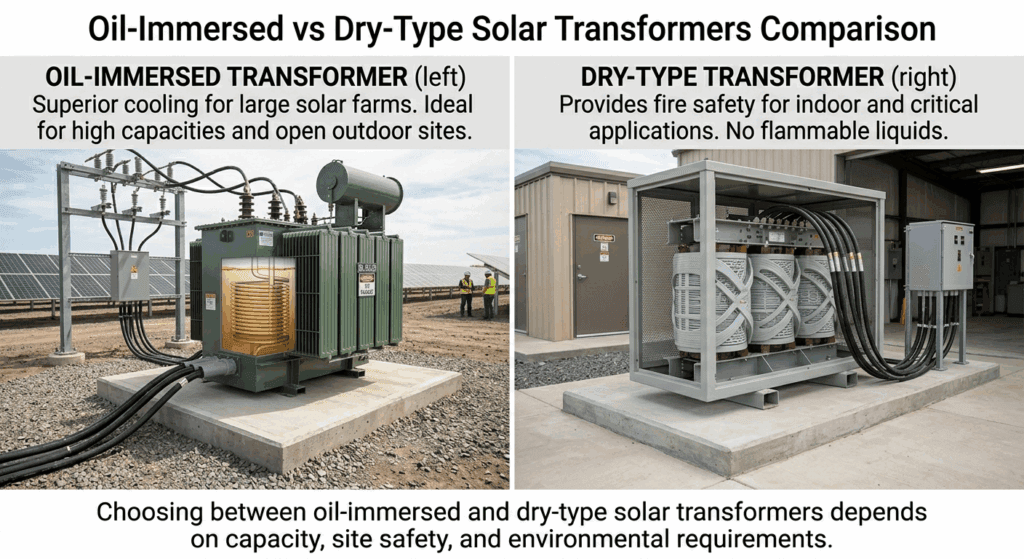
Oil-Immersed (Liquid-Filled) Transformers
These remain the most common for utility-scale solar farms due to excellent cooling and efficiency at higher ratings (typically above 1 MVA). Mineral oil or environmentally friendly ester fluids (e.g., FR3 vegetable oil) provide insulation and heat dissipation.
المزايا:
- Superior thermal performance for large loads.
- Lower cost per kVA for high-capacity units.
- Proven longevity in outdoor environments with proper maintenance.
Common cooling methods: ONAN (Oil Natural Air Natural) or ONAF (Oil Natural Air Forced).
For most utility-scale solar farms, oil-immersed solar transformers remain the preferred choice due to superior cooling and cost-efficiency.
Dry-Type Transformers (Cast Resin)
Dry-type units use epoxy resin-encapsulated windings, eliminating oil-related fire and spill risks. They excel in urban, indoor, or environmentally sensitive locations.
المزايا:
- Higher fire safety (no flammable oil).
- Lower maintenance (no oil testing).
- Suitable for harsh or polluted environments when properly enclosed.
Limitations: Generally more expensive and less efficient at very large ratings compared to oil-immersed.
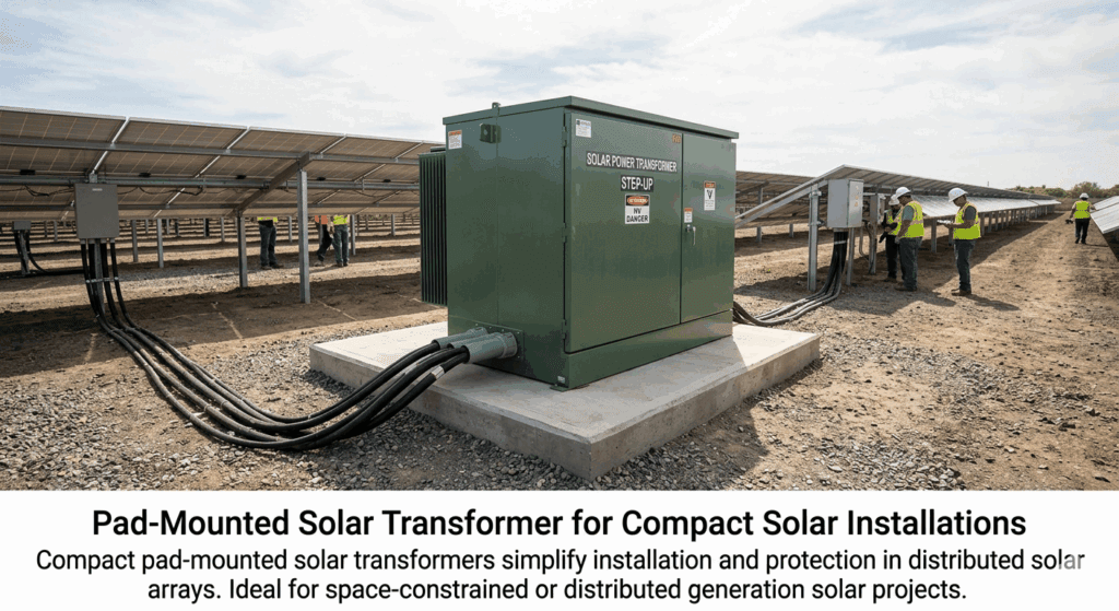
Pad-Mounted Transformers
These compact, tamper-resistant units combine the transformer with protective gear in a ground-level enclosure. They are popular for distributed solar or where space is limited.
They can be oil-filled or dry-type and simplify installation in solar arrays.
Other Variants
- Multiple-winding transformers: Feature two or more LV windings to serve multiple inverters from one HV connection, optimizing space and cost.
- K-rated transformers: Specifically designed with enhanced windings and cooling to handle harmonic loads.
Here is a comparison table of common types:
| نوع المحول | Typical Capacity | طريقة التبريد | Key Advantages | Best For | Drawbacks |
|---|---|---|---|---|---|
| Oil-Immersed | 1–50+ MVA | ONAN/ONAF | High efficiency, cost-effective at scale | Utility-scale solar farms | Oil maintenance, fire risk |
| Dry-Type (Cast Resin) | 0.5–10 MVA | AN/AF | Fire-safe, low maintenance | Indoor, urban, or sensitive sites | Higher cost, limited very large sizes |
| مثبتة على الوسادة | 0.5–5 MVA | Oil or Dry | Compact, tamper-proof, easy install | Distributed generation | Space constraints in some designs |
| Multiple LV Winding | 2–10 MVA | Varies | Connects multiple inverters | Inverter blocks | Custom design required |
Selection often involves balancing efficiency, safety, and total ownership cost. For large solar power plants, oil-immersed units dominate, while dry-type grows in popularity for modular or high-safety projects.
4.Key Differences: Inverter Duty Transformer vs Standard Distribution Transformer
A common mistake is assuming a standard distribution transformer suffices for solar applications. Inverter Duty Transformers (IDT) are engineered specifically for the demands of PV inverters.
Core Differences:
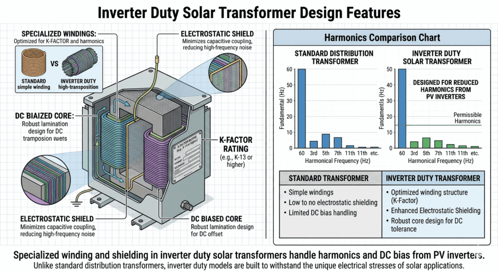
- Harmonic Handling: Inverters generate harmonics and high dv/dt transients. IDTs incorporate K-factor ratings (K-4 common for solar), reinforced windings, and electrostatic shields to mitigate extra heating. Standard transformers (K-1) overheat under the same conditions.
- DC Bias Tolerance: Some inverters inject small DC components, risking core saturation. IDTs use lower flux density designs and better core materials to tolerate this.
- Load Profile: Solar output features daily cycling and partial loading. IDTs often use dual temperature rise ratings (e.g., 55/65°C) for overload capability without excessive aging.
- Power Factor: Inverters operate near unity PF (1.0). Sizing for 0.8 PF (common in traditional loads) leads to oversizing and inefficiency. IDTs are rated accordingly.
- Insulation and Transients: Enhanced insulation systems handle fast voltage rises from PWM switching. Electrostatic shields between HV and LV windings reduce transferred transients.
- الكفاءة والخسائر: IDTs optimize for variable loads, maintaining high efficiency even at 30-50% loading typical in solar.
Using a standard transformer in a solar plant can void warranties, reduce lifespan by 20-50%, and increase losses by several percent annually.
In summary, while a standard unit might appear cheaper upfront, an inverter duty solar transformer delivers better long-term performance and lower total cost of ownership.
Unlike standard distribution transformers, our custom solar transformer solutions are specifically engineered to handle harmonics and DC bias.
5.Critical Selection Criteria for Solar Transformers
Choosing the right solar transformer requires evaluating multiple technical and operational factors.
Capacity and Sizing Basics
Match the transformer kVA to the aggregate inverter AC output, applying a 10-20% margin for overload, future expansion, and derating. Since inverters deliver near unity power factor, size primarily on kW output converted to kVA without assuming 0.8 PF.
Voltage Ratings and Configuration
- LV side: Matches inverter output (e.g., 800V).
- HV side: Aligns with grid or collector voltage (11 kV, 33 kV, etc.).
- Vector group: Common choices include Dyn11 or YNd11 for harmonic blocking and grounding. Delta on LV helps trap triplen harmonics.
Impedance (%Z) typically 6-10% balances fault current limitation and voltage regulation.
Environmental and Site Conditions
Consider ambient temperature (derate above 40°C), altitude, pollution level, and seismic requirements. Outdoor units need robust enclosures (IP55 or better).
Overload and Thermal Performance
Solar plants experience variable loads. Specify dual-rated temperature rise and confirm overload curves with the manufacturer.
Other criteria include:
- Efficiency at different load points.
- Noise levels (especially near populated areas).
- Cooling method suitability.
- Bushings, tap changers (if needed), and monitoring provisions.
A detailed checklist during specification prevents costly redesigns later.
6.Sizing Guide for Solar Transformers with Examples
Proper solar transformer sizing prevents under- or over-utilization.
Basic Formula (Three-phase): kVA = (√3 × Voltage × Current) / 1000
For solar:
- Start with total inverter AC power output in kW.
- At unity PF, kVA ≈ kW.
- Apply margin: 10-20% for overload and expansion.
- Consider harmonics: Use K-rated or derate if needed.
Example 1: 5 MW Solar Plant
- Inverters: 5 × 1 MW units, total AC output 5 MW at PF=1.0.
- Recommended sizing: 5.5–6 MVA (10-20% margin).
- Voltage: LV 800V to HV 33 kV.
- Use oil-immersed ONAN with K-4 rating.
Example 2: Multiple Inverter Block (2.5 MW)
- Two 1.25 MW inverters connected to one transformer with dual LV windings.
- Transformer rating: 2.75 MVA.
- This reduces footprint and connection points.
Common pitfalls:
- Sizing based on DC side or 0.8 PF → oversizing and higher cost.
- Ignoring ambient temperature or harmonics → premature aging.
- No consultation with inverter manufacturer → compatibility issues.
Always perform a power quality study for large projects and verify with both transformer and inverter suppliers. Modern tools and software can simulate load cycles per IEC 60076-7 guidelines.
For precise calculations in complex plants, engage a specialist for electromagnetic transient (EMT) studies.
7.Harmonics, DC Bias, and Power Quality Considerations
Harmonics represent one of the biggest challenges for solar transformers.
Inverters use high-frequency switching, producing current and voltage harmonics even with built-in filters. Cumulative THD can cause:
- Increased eddy current losses (proportional to frequency squared).
- Core and winding overheating.
- Reduced efficiency and lifespan.
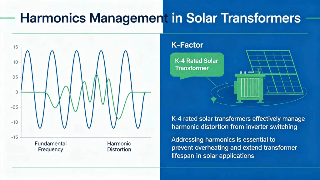
K-Factor quantifies harmonic tolerance (per IEEE C57.110). For most solar applications with modern inverters (THD <5-8%), a K-4 rating suffices. Higher K-9 or K-13 may be needed in older systems or high-distortion scenarios.
DC Bias: Small DC components from inverters can saturate the core, increasing magnetizing current and noise. IDTs mitigate this with lower operating flux density and robust core steel.
Mitigation Strategies:
- Specify electrostatic shields.
- Use delta-wye configurations to block triplen harmonics.
- Consider active or passive harmonic filters if THD exceeds limits.
- Ensure compliance with IEEE 519 at the point of common coupling.
Proper handling of these issues prevents hot spots, insulation degradation, and nuisance tripping.
For detailed guidance on harmonic derating, refer to the IEEE C57.110 standard.
8.Design, Installation, and Best Practices
Effective design goes beyond ratings. Key elements include:
- Reinforced insulation for dv/dt stresses (up to 2400 V/μs in some cases).
- Enhanced cooling margins for thermal cycling.
- Robust mechanical design for transport and seismic loads.
- Monitoring: Winding temperature, oil level, Buchholz relay, etc., for predictive maintenance.
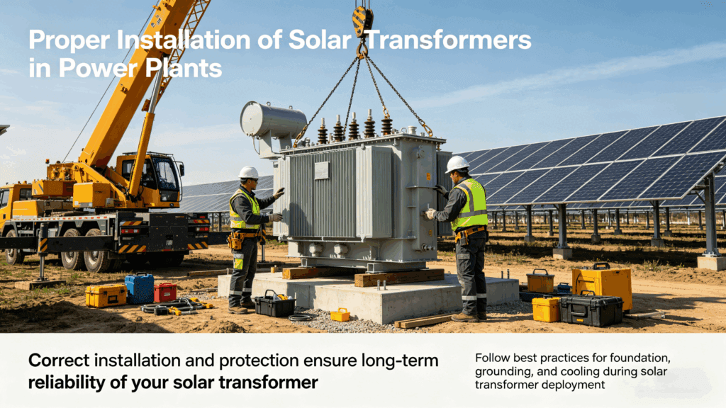
Installation Best Practices:
- Proper foundation and ventilation.
- Correct cable sizing and termination.
- Grounding per vector group and grid codes.
- Protection coordination with inverters and switchgear.
Commissioning should include ratio, polarity, insulation resistance, and no-load/loss tests. For large plants, perform harmonic measurements post-energization.
Regular maintenance — oil analysis for immersed units, thermography, and tightness checks — extends life toward 25-30+ years.
9.Standards and Compliance for Solar Transformers
Compliance ensures safety, performance, and grid acceptance. Relevant standards include:
- IEC 60076 series (power transformers).
- IEEE C57.159-2016: Guide for transformers in distributed PV systems.
- IEEE C57.110 for harmonic derating.
- Local grid codes for interconnection (e.g., voltage ride-through, harmonics limits).
Additional certifications: UL, ANSI, or regional equivalents. For international projects, dual IEC/IEEE compliance may be required.
Specify testing: Routine, type, and special tests (e.g., for harmonics or impulse).
Adhering to these standards reduces risks during permitting and operation.
10.Choosing the Right Supplier for Your Solar Project
Not all manufacturers excel at solar transformers. Look for:
- Proven experience in utility-scale PV projects.
- In-house design capability for custom IDTs.
- Strong after-sales support and spare parts availability.
- References from similar climates or capacities.
- Ability to provide technical simulations and compliance documentation.
A reliable partner offers value engineering, short lead times, and ongoing technical consultation. Factors like delivery reliability matter greatly in fast-track solar projects.
Evaluate total cost of ownership, not just initial price. Quality solar transformers from experienced suppliers minimize lifecycle risks.
Ready to move forward?
Contact our team for a free technical consultation and customized quotation.
11.Conclusion
Selecting the optimal solar transformer for your power plant involves balancing technical requirements, site conditions, and long-term performance. From understanding inverter-specific challenges like harmonics and DC bias to applying proper sizing and choosing between oil-immersed or dry-type designs, a systematic approach ensures reliability and efficiency.

Key takeaways:
- Prioritize inverter duty designs over standard transformers.
- Size based on unity PF with appropriate margins.
- Address harmonics proactively with K-factor and shielding.
- Comply with IEEE C57.159 and IEC standards.
- Partner with experienced suppliers for custom solutions.
Implementing these principles can lower losses, extend asset life, and improve project ROI.
Ready to specify or procure a solar transformer for your next solar power plant? Our team specializes in custom inverter duty transformers tailored to utility-scale PV applications. اتصل بنا today for a free technical consultation, sizing assistance, or detailed quotation. Download our Solar Transformer Selection Checklist to streamline your next project.
Share your experiences or questions in the comments below — what challenges have you faced with transformer selection in solar plants?
We look forward to supporting your renewable energy goals.
See how we have supported successful installations in view our recent solar projects across Asia.