Understanding the transformer voltage ratio is more than just memorizing a math equation; it’s about mastering the “heartbeat” of power distribution. Whether you are troubleshooting a buzzing industrial unit or designing a PCB-mount signal transformer, the ratio defines your success.
Table of Contents
- The Basics: What is Transformer Voltage Ratio?
- The Core Formula: Vp/Vs = Np/Ns
- Step-by-Step Calculation Examples
- Turns Ratio vs. Voltage Ratio: The Nuance
- Real-World Efficiency & Voltage Drop
- Testing the Ratio in the Field
- Conclusion & Summary
1. The Basics: What is Transformer Voltage Ratio?
At its simplest, a transformer is a static piece of hardware that moves electrical energy from one circuit to another through inductively coupled conductors. But here’s the kicker: it doesn’t just “move” energy—it transforms it.
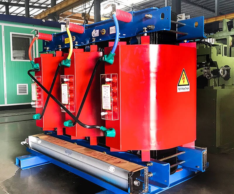
480V in, 120V out — that’s a 4:1 transformer. The turns ratio is simply the relationship between primary and secondary voltage. Choosing the right high-quality industrial transformers ensures your facility maintains a stable voltage ratio even under heavy electrical loads.
Why Does It Matter?
In the world of electrical operation, “close enough” isn’t good enough. If your ratio is off by even 5%, you risk overheating sensitive equipment or, worse, catastrophic insulation failure. We use this ratio to categorize transformers into two main camps:
- Step-Up Transformers: Where the output voltage is higher than the input.
- Step-Down Transformers: Where the output is lower (common in residential chargers).
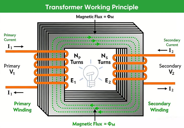
2. The Core Formula: Vp/Vs = Np/Ns
Let’s get into the weeds of the math. In an ideal world—where we pretend physics doesn’t involve heat or resistance—the voltage ratio is directly proportional to the “turns ratio.”
The fundamental equation is:
Vp/Vs = Np/Ns = a
Where:
- Vp: Primary Voltage
- Vs: Secondary Voltage
- Np: Number of turns in the primary winding
- Ns: Number of turns in the secondary winding
- a: Transformation ratio (sometimes written as k)
| Transformer Type | Ratio (a) | Voltage Relationship | Typical Application |
| Step-Down | a > 1 | Vp > Vs | Household Electronics (240V to 12V) |
| Step-Up | a < 1 | Vp < Vs | Power Plant Transmission |
| Isolation | a = 1 | Vp = Vs | Medical Equipment Safety |
Wait—I should clarify something here. In many textbooks, they use a = Np/Ns. However, some IEEE standards might flip this depending on whether you are looking from the high-voltage or low-voltage side.
For this guide, we’ll stick to Primary/Secondary. While our calculation assumes 100% efficiency, understanding ideal transformer principles is the first step before factoring in real-world magnetic impedance.
3. Step-by-Step Calculation Examples
Here’s a real-world situation. You’ve got a transformer on-site. Nameplate? Completely scratched — unreadable.
The math is simple: 2000 to 500 turns gives you a 4:1 ratio.
It’s a classic configuration for step-down transformer applications—taking high voltage from the transmission line and reducing it to a level that’s safe to use on-site.
Scenario A: Finding the Output Voltage
If you apply 240V to the primary, what is the secondary voltage?
- Identify Np and Ns: Np = 2000, Ns = 500.
- Calculate the Ratio (a): 2000 / 500 = 4.
- Apply to Voltage: 240V / 4 = 60V.
Scenario B: The Current Flip
People often forget that while voltage goes down, current (I) goes up. The law of conservation of energy (minus losses) dictates that Pin = Pout.
Actually, let me rephrase that. P = V X I. So:
Vp X Ip = Vs X Is
So here’s how it works: the current ratio is just the voltage ratio flipped upside down. Drop the voltage by a factor of 10, and you boost the current capacity by about 10 times.
Now, getting that ratio right in a specialized industrial setup? That can get tricky. If you’re dealing with voltages that are off the beaten path, our engineering team can step in. We’ll design a custom transformer built specifically for your load requirements..
4. Turns Ratio vs. Voltage Ratio: The Nuance
Are they the same thing? Almost. In a classroom, yes. In the field? No. When I first started as an operator, I assumed if I saw a 10:1 turns ratio, I’d see exactly a 10:1 voltage ratio on my multimeter. I was wrong.
The Соотношение поворотов is a physical constant based on how the copper is wound around the core. The transformer voltage ratio is what you actually measure. Because of “leakage flux” and the resistance of the wire, the measured voltage on the secondary side will always be slightly lower than the theoretical “turns” calculation when the transformer is under load.
5. Real-World Efficiency & Voltage Drop
No transformer is 100% efficient. We have to account for “Voltage Regulation.”
Loss Factors
- Copper Losses (I^2R): Heat generated by the resistance of the wires.
- Core Losses: Hysteresis and eddy currents within the iron core.
- Magnetic Leakage: Not all magnetic lines of force connect the two coils.
| Loss Type | Cause | How to Minimize |
| Eddy Currents | Circulating currents in the core | Use laminated steel cores |
| Hysteresis | Molecular friction in the core | Use high-grade silicon steel |
| Ohmic Loss | Resistance of the copper | Increase wire gauge (thickness) |
If you’re calculating the transformer voltage ratio for a high-load industrial motor, you must account for a 2-5% voltage drop. If you require exactly 120V under load, you may actually need a transformer with a “no-load” output of around 126V.
To get a precise output voltage, you must account for transformer efficiency and losses, such as eddy currents and hysteresis, which vary by core material.
6. Testing the Ratio in the Field
How do you verify this? You use a TTR (Transformer Turns Ratio) Meter.
If you suspect a transformer has a shorted turn (which is a nightmare for heat generation), the voltage ratio will shift.
- Isolate the transformer (Safety first! De-energize everything).
- Apply a low voltage to the high-voltage side.
- Measure the output on the low-voltage side.
- Compare the result to the nameplate.
If your measured voltage ratio is off by more than 0.5%, assume a winding fault.
Stop taking readings. Call the manufacturer—or start sourcing a replacement.
Once it’s swapped out, test it against IEEE standards. That’s how you verify long-term safety.
If your measured ratio is significantly off, it might be time to explore custom transformer solutions tailored to your specific voltage requirements.
7. Conclusion & Summary
Calculating the transformer voltage ratio serves as the bridge between theoretical physics and practical power systems. By applying the formula Vp/Vs = Np/Ns, you can anticipate performance—but always remember to account for real-world losses.
Quick Recap:
- Step-up increases voltage (a < 1).
- Step-down decreases voltage (a > 1).
- Always check your nameplate for the specific “vector group” and “tap settings” which can alter the effective ratio.
Whether you need a standard step-down unit or a high-capacity industrial transformer, we deliver precision-engineered solutions with guaranteed efficiency. Contact our support team for bulk pricing or technical specifications.