Transformer relay coordination is essential for ensuring safe, selective, and reliable operation in medium and low voltage (MV/LV) power distribution systems. Engineers must carefully coordinate transformer characteristics, short-circuit levels, and protection relay settings to prevent unnecessary outages while still isolating faults quickly and effectively.
Without proper coordination, even a minor downstream fault can trip upstream breakers and shut down an entire facility. By combining accurate transformer data, impedance analysis, and time-current coordination (TCC) studies, engineers can design protection schemes that balance equipment safety, operational continuity, and regulatory compliance.
Оглавление
- Introduction
- Fundamentals of Transformer Relay Coordination
- Common Transformer Faults in MV/LV Systems
- Protection Relays Used in Transformer Applications
- Key Parameters That Influence Relay Coordination
- Step-by-Step Transformer Relay Coordination Process
- Special Considerations in Industrial and Solar Systems
- Common Coordination Mistakes
- Practical Engineering Example
- Advanced Considerations in Transformer Relay Coordination
- Testing and Commissioning for Proper Coordination
- Best Engineering Practices for Reliable Transformer Relay Coordination
- FAQ
- Conclusion: Building Reliable MV/LV Systems Through Proper Coordination
1. Introduction
Transformer relay coordination plays a critical role in medium and low voltage (MV/LV) power distribution systems. Engineers must ensure that protection relays operate selectively and isolate faults without causing unnecessary outages. When coordination fails, systems experience nuisance tripping, equipment damage, and costly downtime.
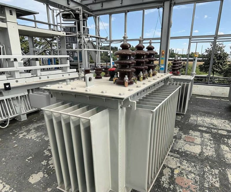
In industrial plants, commercial buildings, and renewable energy projects, transformers connect different voltage levels and form the backbone of power distribution. Protection relays safeguard these transformers against overloads, short circuits, and abnormal operating conditions. However, relays must distinguish between actual faults and temporary phenomena such as transformer inrush current. This distinction defines effective transformer relay coordination.
From practical engineering experience, poor relay settings often cause more problems than hardware defects. Incorrect pickup current, improper time delay, or ignoring transformer impedance can compromise the entire protection scheme. Therefore, engineers must approach transformer relay coordination systematically rather than relying on default relay settings.
This guide explains how to coordinate transformers and protection relays in MV/LV systems using calculation methods, time-current curve analysis, and engineering best practices.
2. Fundamentals of Transformer Relay Coordination
Transformer relay coordination ensures that protection devices operate in a predefined sequence during abnormal conditions. The primary goal is selective fault isolation.
In an MV/LV system, protection layers typically include:
- Utility or upstream feeder protection
- MV switchgear relays
- Transformer protection relays
- LV main breaker protection
- Downstream feeder protection
Each protection level must operate with appropriate timing and current settings.
2.1 What Is Selective Coordination?
Selective coordination means that only the protective device closest to the fault operates, while upstream devices remain energized.
For example:
- If a short circuit occurs on an LV feeder, the LV breaker should trip.
- The transformer MV-side relay should not trip.
- The upstream grid protection should remain unaffected.
Without proper coordination, a minor LV fault may shut down the entire substation.
2.2 Objectives of Transformer Relay Coordination
Engineers typically aim to achieve:
- Transformer thermal protection
- Mechanical protection against short-circuit stress
- Continuity of service
- Personnel safety
- Compliance with IEC or IEEE standards
The following table summarizes these objectives:
| Objective | Why It Matters | Engineering Impact |
|---|---|---|
| Overload Protection | Prevents insulation aging | Продлевает срок службы трансформатора |
| Short Circuit Protection | Prevents winding damage | Avoids catastrophic failure |
| Selective Isolation | Minimizes downtime | Improves system reliability |
| Inrush Discrimination | Prevents nuisance tripping | Maintains system stability |
Effective transformer relay coordination balances all these factors simultaneously.
Protection relays used in MV systems should comply with IEC 60255 protection relay standards to ensure reliable performance and testing accuracy.
3. Common Transformer Faults in MV/LV Systems
Understanding transformer fault behavior allows engineers to design appropriate relay settings.
3.1 Overload Conditions
Overload occurs when the transformer carries current above its rated capacity for extended periods. Thermal stress accumulates in windings and insulation.
Relays must detect overload without tripping during short-term load peaks.
3.2 Internal Short Circuits
Internal faults include:
- Phase-to-phase faults
- Phase-to-ground faults
- Winding-to-core faults
These faults generate high fault currents limited primarily by transformer impedance.
3.3 External Short Circuits
External LV faults reflect to the MV side through the transformer. Relay coordination must ensure that LV protection clears these faults before MV protection operates.
3.4 Transformer Inrush Current
When energizing a transformer, magnetizing inrush current may reach 6 to 12 times rated current. This current:
- Contains high harmonic components
- Lasts several cycles
- Does not indicate a fault
Poor relay coordination may interpret inrush as a short circuit.
| Condition | Current Magnitude | Duration | Relay Response Needed |
|---|---|---|---|
| Full Load | 1 × rated | Continuous | No trip |
| Inrush | 6–12 × rated | 0.1–1 sec | Block or delay |
| Short Circuit | 10–25 × rated | Sustained | Immediate trip |
Distinguishing between inrush and actual fault current is a key challenge in transformer relay coordination.
4. Protection Relays Used in Transformer Applications
Engineers select protection relays based on transformer size, system configuration, and reliability requirements.
4.1 Overcurrent Relays (OCR)
Overcurrent relays form the most common protection method in MV/LV systems. They operate when current exceeds a preset value.
Types include:
- Definite time overcurrent relay
- Inverse time overcurrent relay
- Extremely inverse curve relay
Inverse curves help coordinate with downstream devices.
4.2 Differential Protection Relays
Differential relays compare current entering and leaving the transformer. If the difference exceeds a threshold, the relay trips.
Engineers commonly apply differential protection to:
- Transformers above 2000 kVA
- Critical industrial loads
- Utility substations
Differential relays offer high sensitivity and fast operation.
4.3 Earth Fault Relays
Ground faults occur frequently in LV systems. Earth fault relays detect residual current and trip accordingly.
Proper sensitivity selection ensures:
- Fault detection
- Avoidance of nuisance trips due to leakage currents
4.4 Thermal Protection
Thermal relays or temperature sensors monitor winding temperature. They complement overcurrent protection.
4.5 Numerical Protection Relays
Modern MV systems use digital relays with programmable settings. These relays support:
- Time-current curve adjustment
- Harmonic restraint for inrush blocking
- Event recording
- Communication protocols
Digital relays significantly improve transformer relay coordination accuracy.
5. Key Parameters That Influence Relay Coordination
Transformer relay coordination depends heavily on transformer electrical characteristics.
5.1 Rated Current Calculation
Engineers calculate rated current using:
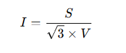
Where:
- S = Transformer rating (kVA)
- V = Line voltage (kV)
Example:
For a 2500 kVA, 20 kV transformer:
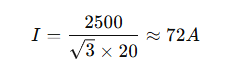
Relay pickup settings must exceed rated current but remain below fault current levels.
5.2 Transformer Impedance (%Z)
Impedance determines short-circuit current magnitude.
Short-circuit current can be estimated by:
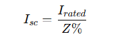
If impedance = 6%:

Higher impedance reduces fault current but increases voltage drop.
Relay coordination must consider this relationship.
5.3 Time-Current Coordination (TCC) Curves
Engineers use TCC curves to visualize coordination.
A properly coordinated system ensures:
- Downstream device curve lies below upstream device curve
- Adequate time margin exists between operations
- Transformer thermal curve is protected
TCC analysis forms the backbone of professional transformer relay coordination studies.
6. Step-by-Step Transformer Relay Coordination Process
Engineers should approach transformer relay coordination as a structured engineering study rather than a simple relay setting task. A systematic process reduces errors and ensures selective protection in MV/LV systems.
Step 1 – Determine Transformer Rated Current
Start by calculating the transformer full load current using the rated kVA and voltage.
This value defines:
- Continuous operating current
- Minimum relay pickup threshold
- Thermal protection reference
Relay pickup must exceed rated current to prevent nuisance tripping during normal load fluctuations.
As a general engineering practice:
- Set overload pickup at 110–125% of rated current
- Verify against transformer thermal curve
Accurate rated current calculation forms the foundation of transformer relay coordination.
Step 2 – Calculate Maximum Short Circuit Current
Next, determine the maximum available fault current at the transformer terminals.
Use transformer impedance (%Z) to estimate the symmetrical short circuit current.
Short circuit current determines:
- Instantaneous trip settings
- Breaker interrupting capacity
- Relay curve selection
Engineers must also consider upstream network contribution. In MV systems connected to strong utility grids, fault levels may significantly exceed transformer-limited values.
Failure to evaluate maximum fault current often results in:
- Relay underestimation
- Inadequate protection
- Breaker failure risk
Transformer relay coordination requires both transformer data and system-level fault analysis.
Step 3 – Select Appropriate Relay Type
Relay selection depends on transformer size and criticality.
| Transformer Size | Typical Protection Scheme |
|---|---|
| < 1000 kVA | Overcurrent relay only |
| 1000–2500 kVA | Overcurrent + Earth fault |
| > 2500 kVA | Overcurrent + Differential |
| Critical Loads | Differential + Backup OCR |
For industrial MV/LV systems, numerical relays provide flexibility and better coordination performance.
Modern relays allow:
- Adjustable time-current curves
- Harmonic restraint for inrush blocking
- Event logging for analysis
Proper relay selection enhances transformer relay coordination reliability.
Step 4 – Set Relay Pickup Current
Engineers typically apply the following logic:
Overload Protection Setting
Pickup = 1.1–1.25 × Rated Current
This prevents false trips during:
- Temporary overload
- Motor starting
- Short-term demand peaks
Short Circuit Protection Setting
Instantaneous trip must:
- Remain above inrush current
- Remain below minimum fault current
In practice:
- Inrush may reach 8–12 × rated current
- Internal fault may exceed 15–20 × rated current
Engineers often introduce a short intentional time delay to ride through inrush.
Transformer relay coordination must carefully distinguish between these two conditions.
Step 5 – Adjust Time Delay for Selectivity
Time grading ensures selective operation between upstream and downstream devices.
Engineers usually maintain a coordination margin of:
- 0.2 to 0.4 seconds between protection levels
For example:
- LV feeder breaker: 0.2 sec
- LV main breaker: 0.4 sec
- Transformer MV relay: 0.6 sec
- Upstream feeder relay: 0.8 sec
The exact margin depends on breaker characteristics and standards.
Time grading directly supports selective transformer relay coordination.
Step 6 – Verify Using TCC Curves
Time-current coordination (TCC) analysis visually confirms protection performance.
Engineers plot:
- Transformer thermal damage curve
- Downstream device curve
- Transformer relay curve
- Upstream relay curve
A properly coordinated system satisfies:
- Downstream curves operate first
- Transformer curve protects thermal limits
- Upstream protection acts as backup
TCC analysis provides professional validation of transformer relay coordination.
7. Special Considerations in MV/LV Applications
Real-world systems introduce complexities beyond theoretical calculations.
7.1 Transformer Relay Coordination in Box Substations
Box substations integrate:
- MV switchgear
- Transformer
- LV distribution panel
Coordination challenges include:
- Limited space for protection devices
- Integrated protection logic
- Compact switchgear design
In these systems, engineers must coordinate:
- MV incoming protection
- Transformer protection
- LV outgoing feeders
Proper transformer relay coordination prevents entire substation shutdown due to a single LV feeder fault.
7.2 Industrial Plant Applications
Industrial systems introduce additional coordination factors:
- Large motor starting currents
- Variable frequency drives
- Harmonics
- Intermittent high loads
Motor starting current may reach 6–7 times rated current. Without proper time delay, relays may trip unnecessarily.
Engineers must analyze:
- Starting duration
- Load profile
- Coordination with motor protection relays
Transformer relay coordination in industrial plants requires system-level thinking.
7.3 Solar Power Plant Transformer Protection
Solar plants present unique challenges:
- Reverse power flow
- Intermittent generation
- Harmonic distortion
- Grid code compliance
In grid-connected PV systems, transformer protection must coordinate with:
- Inverter protection logic
- Grid interconnection relays
- Utility requirements
During energization after grid restoration, inrush current combined with inverter synchronization may create complex transient conditions.
Proper transformer relay coordination prevents unwanted disconnection from the grid.
8. Common Mistakes in Transformer Relay Coordination
Even experienced engineers sometimes overlook critical aspects.
8.1 Ignoring Transformer Impedance
Some engineers use generic impedance values instead of manufacturer data.
This practice may:
- Overestimate fault current
- Set relay pickup too high
- Reduce protection sensitivity
Accurate impedance data ensures reliable coordination.
8.2 Setting Pickup Too Close to Rated Current
If pickup equals rated current:
- Minor load fluctuations cause tripping
- System reliability decreases
Always allow adequate margin above full load current.
8.3 Neglecting Inrush Current
Failure to account for inrush current causes frequent nuisance tripping during energization.
Modern numerical relays offer harmonic restraint to block inrush. Engineers should enable and test this feature.
8.4 Poor Upstream-Downstream Coordination
Without time grading:
- Upstream breaker may trip before LV feeder
- Entire facility may lose power
Selective transformer relay coordination prevents cascading outages.
8.5 Not Updating Settings After System Expansion
When adding:
- Additional feeders
- Larger motors
- Parallel transformers
Engineers must re-evaluate relay coordination.
Protection settings that worked initially may no longer remain valid.
9. Practical Engineering Example – MV Transformer Relay Coordination
Consider the following system:
- Transformer rating: 2500 kVA
- Voltage: 20 kV / 0.4 kV
- Impedance: 6%
- System type: Industrial MV/LV distribution
Step 1 – Rated Current (MV Side)
Step 2 – Short Circuit Current
Step 3 – Relay Pickup Setting
Overload pickup:
1.2 × 72 = 86 A
Instantaneous setting:
Above inrush (assume 8 × 72 = 576 A)
Set instantaneous at 700–800 A
Step 4 – Time Delay
Coordinate with LV main breaker curve.
Maintain 0.3 second grading margin.
Example Coordination Table
| Параметр | Ценить |
|---|---|
| Rated Current | 72 A |
| Overload Pickup | 86 A |
| Inrush Estimate | 576 A |
| Instantaneous Setting | 750 A |
| Max Fault Current | 1200 A |
This structured method ensures effective transformer relay coordination.
10. Advanced Considerations in Transformer Relay Coordination
In real MV/LV systems, engineers often face scenarios that require deeper analysis beyond basic pickup and time delay settings.
10.1 Coordination with Upstream Utility Protection
When a transformer connects directly to a utility MV feeder, coordination must align with:
- Utility relay settings
- Recloser timing
- Grid short-circuit levels
Utility systems may use fast-acting protection schemes. If transformer relay timing overlaps improperly, nuisance outages may occur.
Engineers should:
- Obtain utility protection data
- Compare upstream TCC curves
- Maintain sufficient time margin
Transformer relay coordination must integrate with the broader network protection philosophy.
10.2 Parallel Transformer Operation
When operating transformers in parallel, coordination complexity increases.
Engineers must consider:
- Load sharing
- Circulating currents
- Fault contribution from both units
In a parallel configuration:
- A fault on one transformer may draw current from the other
- Differential protection becomes critical
- Backup overcurrent protection must coordinate carefully
| Scenario | Protection Risk | Recommended Solution |
|---|---|---|
| Internal fault in one transformer | Fault current contribution from parallel unit | Differential relay |
| Unequal impedance | Load imbalance | Matching impedance design |
| Bus fault | High combined fault level | Verify breaker rating |
Transformer relay coordination in parallel systems requires detailed fault studies.
10.3 Backup Protection Strategy
Every transformer protection scheme must include backup protection.
Primary protection may fail due to:
- Relay malfunction
- CT failure
- Breaker mechanical failure
Backup protection ensures fault clearance if primary protection does not operate.
Common backup strategies:
- Upstream time-delayed overcurrent relay
- Breaker failure protection
- Redundant differential relays in critical systems
Engineers must ensure that backup protection operates slower than primary protection but fast enough to prevent equipment damage.
11. Testing and Commissioning for Proper Coordination
Design calculations alone do not guarantee reliable transformer relay coordination. Field verification is essential.
11.1 Secondary Injection Testing
Engineers simulate current signals to verify:
- Pickup accuracy
- Time delay performance
- Instantaneous trip behavior
This test confirms that relay settings match engineering calculations.
11.2 Primary Injection Testing
Primary injection validates the entire protection chain, including:
- Current transformers (CTs)
- Wiring integrity
- Breaker operation
Although more complex and expensive, primary testing provides higher confidence.
11.3 Inrush Blocking Verification
For transformers with harmonic restraint:
- Engineers energize the transformer
- Monitor relay response
- Confirm that inrush does not cause tripping
Failure to test inrush blocking often leads to nuisance trips during commissioning.
11.4 Documentation and Setting Records
Proper documentation supports long-term reliability.
Maintain records of:
- Relay model
- Firmware version
- Setting parameters
- TCC curves
- Test results
Accurate documentation simplifies future system upgrades and troubleshooting.
12. Best Engineering Practices for Reliable Transformer Relay Coordination
Based on industry practice and field experience, engineers should follow these principles.
12.1 Always Use Manufacturer Transformer Data
Use actual:
- Impedance (%Z)
- Loss data
- Thermal curves
- Inrush characteristics
Avoid generic assumptions. Small deviations can significantly affect relay settings.
12.2 Maintain Coordination Margin
Allow sufficient time grading between protection levels.
Typical engineering margin:
- 0.2–0.4 seconds
This margin prevents cascading outages.
12.3 Perform Full Coordination Study for Critical Systems
For industrial plants, data centers, and renewable energy substations:
- Conduct full short-circuit study
- Perform TCC analysis
- Validate protection selectivity
Professional coordination studies significantly improve system reliability.
12.4 Review Settings After System Changes
When modifying:
- Transformer capacity
- Feeder configuration
- Motor loads
- Parallel operation
Recalculate fault levels and verify transformer relay coordination.
Protection design must evolve with system expansion
12.5 Integrate Protection with Overall Power System Design
Transformer relay coordination should align with:
- Grounding system design
- Arc flash study
- Equipment rating
- Operational philosophy
Protection cannot be designed in isolation.
13.FAQ
What is transformer relay coordination?
Transformer relay coordination ensures that protection devices operate selectively to isolate faults while preventing unnecessary shutdown of upstream equipment in MV/LV systems.
How do you calculate relay pickup current for a transformer?
Engineers calculate transformer rated current using the kVA and voltage formula. They then set relay pickup at approximately 110–125% of rated current to avoid nuisance tripping.
Why does transformer inrush current trip the relay?
Inrush current can reach 6–12 times rated current during energization. If the relay does not include harmonic restraint or time delay, it may interpret inrush as a fault.
How does transformer impedance affect protection settings?
Transformer impedance limits short-circuit current. Lower impedance produces higher fault current, which influences relay instantaneous and time-delay settings.
Do small transformers require differential protection?
Small transformers below 1000 kVA typically use overcurrent protection only. Larger or critical transformers often require differential protection for fast internal fault detection.
What is the role of TCC curves in coordination?
Time-current coordination curves visually demonstrate how protective devices operate relative to each other and the transformer thermal limit. Engineers use TCC analysis to validate selective coordination.
14. Conclusion: Building Reliable MV/LV Systems Through Proper Coordination
Transformer relay coordination forms the foundation of safe and reliable MV/LV power distribution systems. Engineers must balance protection sensitivity, selectivity, and system continuity.
Proper coordination requires:
- Accurate transformer data
- Correct short-circuit calculation
- Appropriate relay selection
- Time grading between devices
- TCC verification
- Field testing
When engineers apply systematic analysis and professional coordination studies, they significantly reduce equipment damage, minimize downtime, and improve long-term operational stability.
In industrial facilities, commercial buildings, renewable energy plants, and box substations, well-executed transformer relay coordination ensures that faults remain localized and power systems remain resilient.
Protection design should never rely on default settings. Instead, engineers must approach coordination as a comprehensive engineering process supported by calculation, analysis, and verification.
Reliable power distribution begins with proper transformer relay coordination.