1.Introduction
As utility-scale photovoltaic projects continue to expand worldwide, the importance of selecting the right Solar Farm Transformer has become more critical than ever. In a 10MW solar power plant, transformers are not simply auxiliary electrical equipment. They are essential components that directly influence system efficiency, grid compatibility, long-distance transmission performance, operational reliability, and overall project return on investment.
A poorly designed transformer system can result in excessive power losses, overheating, voltage instability, frequent maintenance issues, and even grid connection failures. On the other hand, a properly engineered transformer solution helps maximize energy output, reduce operational costs, improve system stability, and ensure long-term project success.
In modern utility-scale solar farms, transformers are used throughout the electrical infrastructure, including inverter step-up applications, medium-voltage collection systems, compact substations, and grid interconnection substations. Whether the project uses centralized or string inverter architecture, transformer sizing and configuration remain among the most important design considerations.
This guide explains how to design and select the right Solar Farm Transformer for a 10MW photovoltaic project. It covers transformer sizing, voltage selection, transformer types, electrical configurations, loss reduction strategies, protection requirements, and key engineering considerations for utility-scale PV plants.
Tabla de contenido
- Introducción
- Overview of a 10MW Solar Farm Electrical System
- Why Solar Farm Transformers Are Important
- Transformer Sizing for 10MW PV Projects
- Common Voltage Levels in Solar Farms
- Types of Transformers Used in Solar Power Plants
- Solar Farm Transformer Configuration Options
- Key Design Considerations for Utility-Scale Solar Transformers
- Transformer Loss Reduction Strategies
- Protection Systems for Solar Farm Transformers
- Common Transformer Design Mistakes
- How to Choose a Reliable Solar Transformer Supplier
- Future Trends in Solar Farm Transformer Technology
- Conclusión
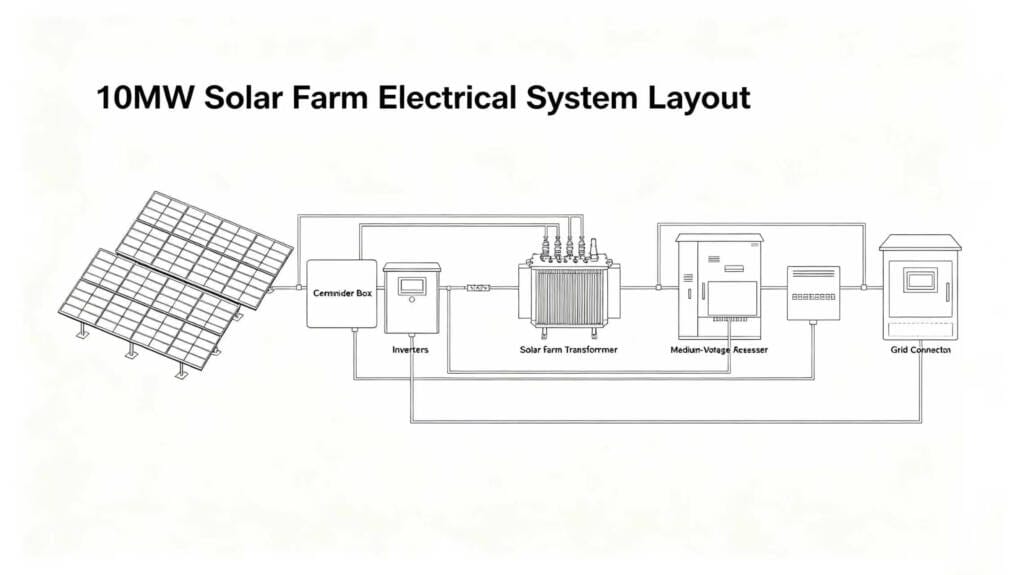
2.Overview of a 10MW Solar Farm Electrical System
A 10MW photovoltaic power plant consists of multiple electrical subsystems working together to convert solar energy into grid-compatible electricity. Understanding the overall system architecture is essential before selecting a Solar Farm Transformer.
The typical electrical system includes:
| Componente | Función |
|---|---|
| Solar Panels | Convert sunlight into DC electricity |
| Combiner Boxes | Combine multiple DC strings |
| Inverters | Convert DC power into AC power |
| Step-Up Transformers | Increase voltage for transmission |
| MV Switchgear | Provide protection and isolation |
| Substation | Connect the plant to the utility grid |
| Monitoring System | Track plant performance |
In most utility-scale projects, solar panels generate low-voltage DC electricity that is converted to AC power by inverters. The output voltage from the inverter is usually between 400V and 800V. Since this voltage is too low for efficient power transmission, a PV Plant Transformer is used to step up the voltage to medium-voltage levels such as 11kV, 22kV, or 33kV.
The electricity is then transmitted through a medium-voltage collection network toward the main substation before being connected to the utility grid.
The transformer system therefore serves as the bridge between solar generation equipment and the utility transmission network.
Modern photovoltaic plants are typically designed according to international electrical standards published by the Comisión Electrotécnica Internacional (IEC).
Need a customized electrical solution for your solar farm project?
👉Contact our team for professional transformer and substation support.
3.Why Solar Farm Transformers Are Important
The role of a Solar Power Transformer extends far beyond voltage conversion. In utility-scale solar projects, transformers directly affect:
- Energy efficiency
- Grid stability
- Equipment protection
- Power quality
- Transmission losses
- Long-term operating costs
Without proper transformer design, even a high-performance solar plant may experience operational inefficiencies and unstable grid interaction.
Utility-scale renewable energy projects must comply with grid interconnection requirements established by regional power authorities and grid operators.
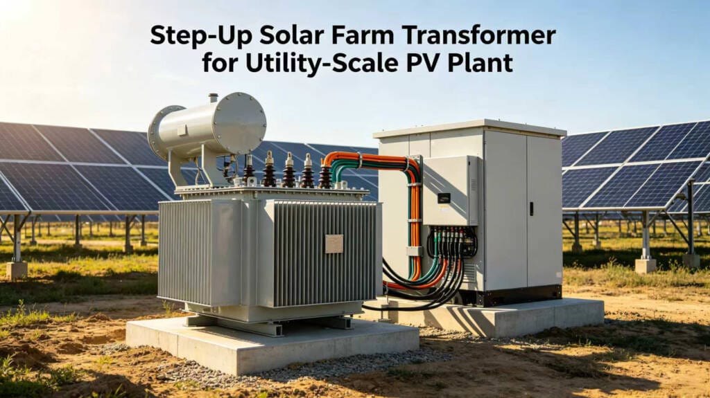
Voltage Step-Up Function
One of the primary functions of a Utility Scale Solar Transformer is stepping up low inverter voltage to medium or high voltage suitable for transmission.
Por ejemplo:
| Equipment | Typical Voltage |
|---|---|
| Inverter Output | 800V |
| Collection System | 33kV |
| Grid Connection | 110kV |
Higher transmission voltage reduces current and minimizes cable losses across the solar farm.
Improving Transmission Efficiency
Long-distance power transmission at low voltage leads to significant energy losses. A properly sized Solar Substation Transformer reduces current flow and minimizes heat losses in cables and switchgear.
This becomes especially important in large solar farms where collection circuits may extend across several kilometers.
Supporting Grid Compliance
Modern utility grids require solar plants to comply with strict technical requirements, including:
- Regulación de voltaje
- Frequency stability
- Reactive power compensation
- Harmonic control
- Fault ride-through capability
A properly engineered Transformer for Solar Farm applications helps maintain stable grid performance and ensures compliance with regional utility standards.
Looking for high-efficiency solar farm transformers for utility-scale projects?
👉Request a technical consultation today.
4.Transformer Sizing for 10MW PV Projects
Transformer sizing is one of the most important engineering tasks in solar farm design. Undersized transformers may overheat during peak generation, while oversized transformers increase unnecessary capital costs and reduce efficiency under partial load conditions.
The transformer capacity must match the plant’s expected operating profile, environmental conditions, and future expansion plans.
Determining Plant Capacity
A 10MW solar farm typically refers to the AC export capacity of the plant. However, the DC installed capacity may be higher depending on the DC/AC ratio.
Ejemplo:
| Parameter | Value |
|---|---|
| AC Capacity | 10MW |
| DC Capacity | 12MWp |
| DC/AC Ratio | 1.2 |
Because PV modules rarely operate at maximum power continuously, developers often oversize the DC side to improve annual energy yield.
This affects Solar Farm Transformer Design because transformers must safely handle peak inverter output.
Transformer Loading Factor
Most utility-scale transformers are designed to operate between 70% and 90% loading for optimal efficiency.
Typical recommendations:
| Loading Range | Condition |
|---|---|
| Below 50% | Inefficient |
| 70%–90% | Optimal |
| Above 100% | Risk of overheating |
For a 10MW project, developers may select:
- 1 × 10MVA transformer
- 2 × 5MVA transformers
- 5 × 2MVA transformers
The final configuration depends on project layout, redundancy requirements, maintenance strategy, and budget.
Environmental Factors
Transformer sizing must also consider:
- Ambient temperature
- Altitude
- Solar irradiance
- Ventilation conditions
- Harmonic distortion from inverters
High ambient temperatures significantly affect transformer cooling performance in solar farms located in desert or tropical regions.
5.Common Voltage Levels in Solar Farms
Voltage selection is another critical part of Solar Transformer Design.
Different regions and utilities use different voltage standards depending on grid infrastructure and project size.
| System Section | Common Voltage |
|---|---|
| Inverter Output | 400V / 690V / 800V |
| MV Collection | 11kV / 22kV / 33kV |
| Grid Interconnection | 66kV / 110kV / 132kV |
Medium Voltage Collection Systems
For most 10MW projects, 33kV is one of the most widely used medium-voltage collection levels because it provides a good balance between:
- Cable cost
- Power losses
- Equipment availability
- Grid compatibility
High Voltage Grid Connection
The final export voltage depends on utility requirements.
Smaller projects may connect at 33kV or 66kV, while larger utility-scale plants often use:
- 110kV
- 132kV
- 220kV
A dedicated Solar Farm Transformer substation is typically required for high-voltage interconnection.
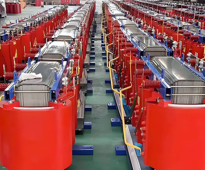
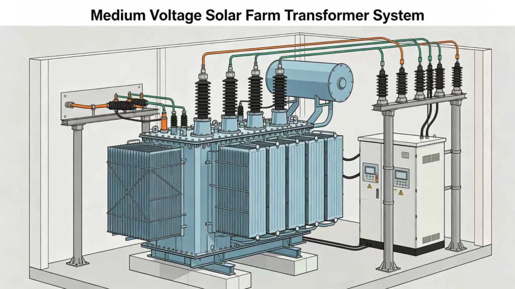
6.Types of Transformers Used in Solar Power Plants
Several transformer types are commonly used in photovoltaic projects.
Each transformer type serves different operational and installation requirements.
Oil Immersed Transformers
Oil immersed transformers are widely used in utility-scale solar farms because of their:
- Alta eficiencia
- Excellent cooling capability
- Strong overload performance
- Long service life
These transformers are suitable for outdoor applications and high-capacity systems.
Advantages include:
- Better thermal performance
- Temperatura de funcionamiento más baja
- Reduced energy losses
- High reliability
Dry Type Transformers
Dry type transformers are commonly installed in indoor substations or environmentally sensitive areas.
Los beneficios incluyen:
- No oil leakage risk
- Lower fire hazard
- Reduced environmental concerns
However, dry type transformers generally have lower overload capacity compared to oil immersed designs.
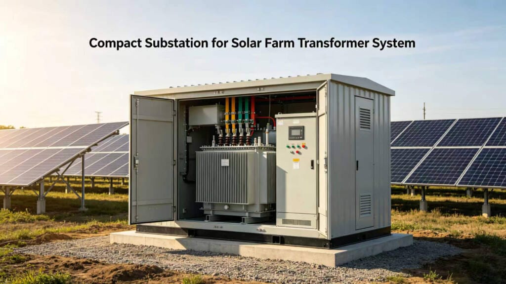
Pad Mounted Transformers
A Pad Mounted Transformer integrates medium-voltage and low-voltage compartments into a compact outdoor enclosure.
These transformers are popular in distributed solar farm layouts because they offer:
- Space-saving installation
- Improved safety
- Simplified maintenance
- Reduced civil construction cost
Compact Substations
Compact substations combine:
- Transformador
- MV switchgear
- LV distribution
- Protection system
into a single integrated unit.
This configuration simplifies installation and reduces project construction time.
7.Solar Farm Transformer Configuration Options
Different transformer configurations provide different operational benefits.
Centralized Transformer Design
In centralized systems, large central inverters connect to one or two high-capacity transformers.
Ventajas
- Lower equipment count
- Simplified maintenance
- Lower initial equipment cost
Disadvantages
- Single-point failure risk
- Longer cable routes
- Reduced redundancy
Distributed Transformer Design
Distributed architecture uses multiple smaller transformers installed across the solar farm.
Ventajas
- Improved redundancy
- Reduced cable losses
- Easier expansion
- Better fault isolation
Disadvantages
- Higher equipment quantity
- Increased maintenance points
Example Configuration
| Configuration | Solicitud |
|---|---|
| 1 × 10MVA | Centralized solar plant |
| 2 × 5MVA | Redundant design |
| 5 × 2MVA | Distributed architecture |
The best solution depends on project goals and site conditions.
8.Key Design Considerations for Utility-Scale Solar Transformers
Transformer design for solar applications requires careful attention to operating conditions that differ from traditional industrial loads.
Harmonic Distortion
Solar inverters generate harmonics that can increase transformer heating and reduce efficiency.
Transformer designers must consider:
- K-factor rating
- Additional cooling capacity
- Harmonic filtering
Failure to address harmonics may shorten transformer lifespan.
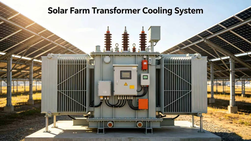
Ambient Temperature
Solar farms are frequently located in high-temperature environments with intense sunlight exposure.
Important considerations include:
- ONAN or ONAF cooling
- Radiator sizing
- Ventilation clearance
- Thermal insulation
Corrosion Protection
Coastal and desert environments may accelerate equipment corrosion.
Protective measures include:
- Anti-corrosion coatings
- Stainless steel hardware
- UV-resistant paint systems
Efficiency Requirements
Transformer losses directly affect plant profitability.
Two major loss categories include:
| Tipo de pérdida | Descripción |
|---|---|
| No-Load Loss | Core losses during energization |
| Load Loss | Copper losses during operation |
High-efficiency Solar Farm Transformers reduce long-term operational costs.
9.Transformer Loss Reduction Strategies
Reducing transformer losses is essential for improving solar farm profitability.
Even a small increase in transformer efficiency can significantly improve lifetime energy output.
Using High-Efficiency Core Materials
Modern transformers often use:
- Grain-oriented silicon steel
- Amorphous metal cores
These materials reduce no-load losses and improve efficiency.
Optimizing Transformer Loading
Operating transformers near optimal load levels improves efficiency and reduces thermal stress.
Oversized transformers may experience excessive no-load losses during low irradiance conditions.
Reducing Cable Distance
Distributed transformer layouts help reduce medium-voltage cable losses across large solar farms.
Shorter cable routes improve:
- Energy efficiency
- Voltage stability
- Installation cost
10.Protection Systems for Solar Farm Transformers
Transformer protection systems are critical for preventing equipment damage and ensuring operational safety.
Protección contra sobrecorriente
Protective relays detect excessive current caused by:
- Short circuits
- Overloads
- Equipment failure
Differential Protection
Differential protection compares incoming and outgoing current to detect internal transformer faults.
This protection is especially important for large utility-scale transformers.
Surge Protection
Lightning strikes and switching surges may damage transformer insulation.
Surge arresters are installed to protect the transformer winding system.
Monitoring Systems
Modern transformers may include:
- Temperature monitoring
- Oil level sensors
- Gas relays
- Remote SCADA integration
Real-time monitoring improves predictive maintenance and operational reliability
11.Common Transformer Design Mistakes
Improper transformer selection can negatively affect project performance for decades.
Undersized Transformers
Undersized transformers may suffer from:
- Excessive heating
- Vida útil reducida
- Frequent trips
- Energy losses
Ignoring Harmonics
Failure to account for inverter harmonics may cause overheating and insulation failure.
Poor Cooling Design
Insufficient cooling clearance or ventilation can reduce transformer reliability.
Incorrect Voltage Selection
Improper voltage design increases:
- Cable losses
- Equipment costs
- Grid integration complexity
12.How to Choose a Reliable Solar Transformer Supplier
Selecting the right transformer supplier is just as important as selecting the right transformer design.
A reliable manufacturer should provide:
| Capability | Importancia |
|---|---|
| IEC/ANSI Compliance | Meets international standards |
| Factory Testing | Ensures product reliability |
| Engineering Support | Provides custom solutions |
| Export Experience | Simplifies global logistics |
| After-Sales Service | Reduces operational risk |
Factory Testing Requirements
Important tests include:
- Routine tests
- Temperature rise tests
- Impulse tests
- Partial discharge tests
Third-party certification further improves project confidence.
Custom Engineering Capability
Every solar project has unique requirements.
An experienced supplier should support:
- Customized voltage ratings
- Special cooling systems
- Compact substation integration
- High-temperature operation
- Grid-specific requirements
13.Future Trends in Solar Farm Transformer Technology
As solar farms continue to grow in size and complexity, transformer technology is also evolving.
Future trends include:
- Smart transformers
- Digital monitoring systems
- Eco-friendly insulating fluids
- Higher efficiency materials
- Compact modular substations
Digital monitoring allows predictive maintenance and improves long-term asset management.
Meanwhile, low-loss transformer technologies continue helping developers maximize project ROI.
14.Conclusion
A properly engineered Solar Farm Transformer system is essential for the performance, efficiency, and reliability of any utility-scale photovoltaic project.
From transformer sizing and voltage selection to cooling design and protection systems, every engineering decision directly affects long-term project profitability and grid performance.
For 10MW solar farms, selecting the right transformer configuration helps reduce energy losses, improve operational stability, simplify maintenance, and ensure compliance with utility requirements.
Whether the project uses oil immersed transformers, compact substations, or distributed pad mounted transformer systems, working with an experienced transformer manufacturer is critical for long-term project success.
As utility-scale solar installations continue expanding worldwide, high-efficiency and grid-ready transformer solutions will remain a key part of modern renewable energy infrastructure.
Need a Reliable Solar Farm Transformer Solution?