1.Introduction
Der Integrated Inverter Transformer is transforming how modern photovoltaic (PV) power plants are designed and operated. In the rapidly growing solar energy sector, PV power plants continue to face major challenges: energy losses during power conversion and transmission, high installation and maintenance costs, complex site coordination, and pressure to reduce Levelized Cost of Energy (LCOE). As utility-scale and commercial & industrial (C&I) PV projects scale into the hundreds of megawatts, traditional separated inverter and transformer setups are increasingly seen as bottlenecks.
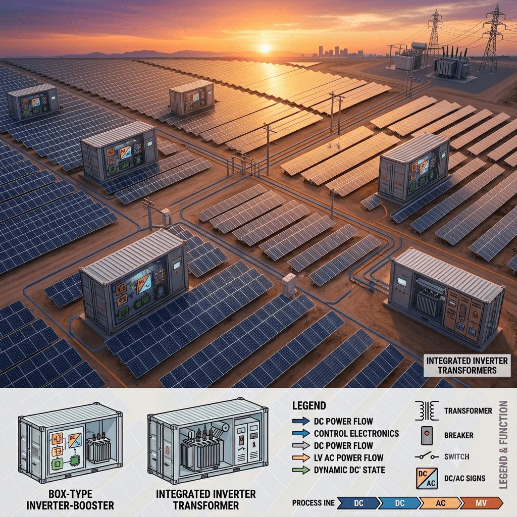
Box-Type Inverter-Booster Integrated Machine solutions — centered on the Integrated Inverter Transformer — address these issues by combining the inverter, step-up transformer, medium-voltage switchgear, and auxiliary systems into a single, compact, factory-preassembled enclosure. This all-in-one approach significantly reduces losses, streamlines deployment, and enhances overall PV plant efficiency.
This comprehensive guide explores the Integrated Inverter Transformer in depth. We will examine its design, technical workings, performance advantages, and practical applications. Whether you are a project developer, EPC contractor, or renewable energy investor, understanding this technology can help optimize your next solar project for higher yields and lower costs.
According to recent analyses, optimizing power conversion and transformation stages is one of the most effective ways to lower the Levelized Cost of Energy (LCOE) in large-scale solar projects
Inhaltsverzeichnis
- Einführung
- What Is a Box-Type Inverter-Booster Integrated Machine?
- The Evolution from Traditional Designs to Integrated Inverter Transformer Solutions
- Technical Principles: How Transformer + Inverter Integration Works
- Key Advantages: How Integrated Inverter Transformer Technology Boosts PV Plant Efficiency
- Performance Comparison: Integrated Inverter Transformer vs. Traditional Separate Systems
- Real-World Case Studies and Quantifiable Results
- Selection Guide: Choosing the Right Integrated Inverter Transformer for Your PV Project
- Installation, Maintenance, and Best Practices
- Conclusion: Why Integrated Inverter Transformer Solutions Are the Future of Solar Power Plants
2.What Is a Box-Type Inverter-Booster Integrated Machine?
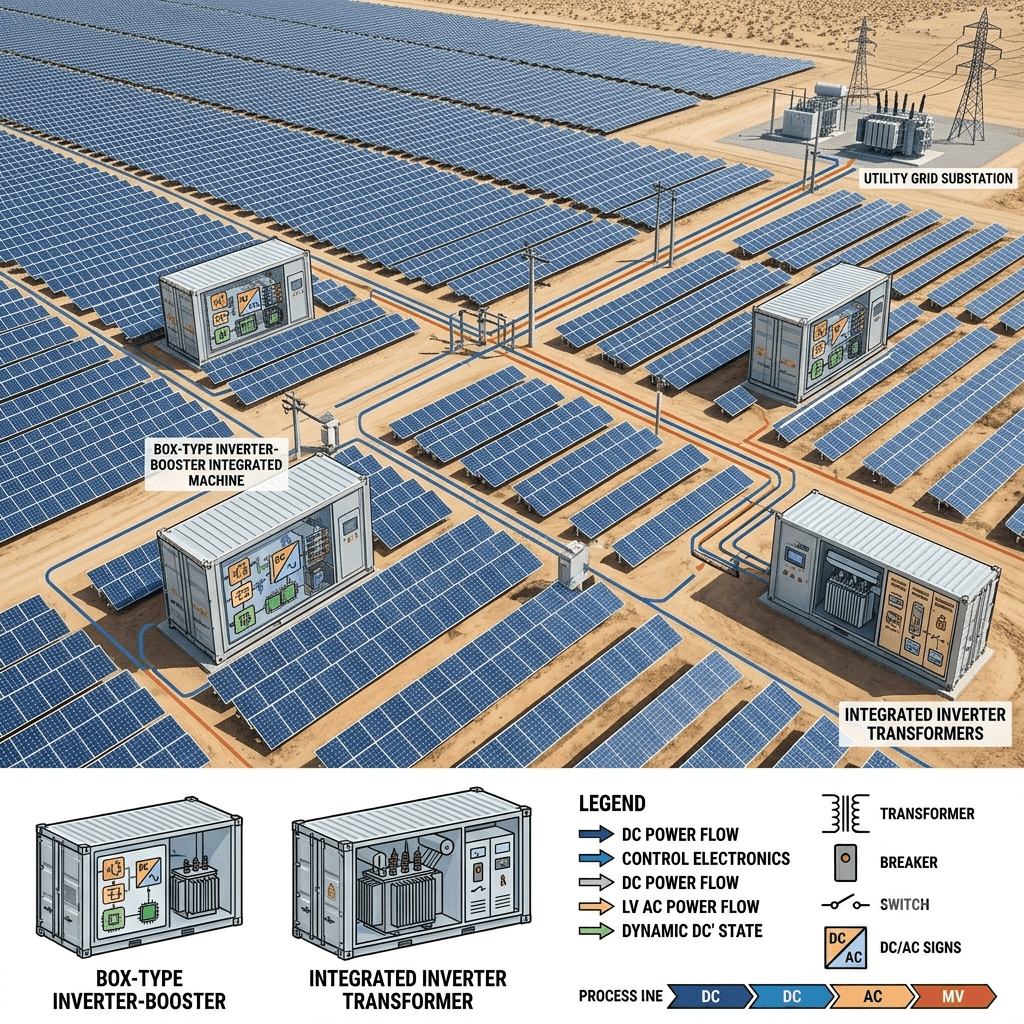
A Box-Type Inverter-Booster Integrated Machine is a fully integrated power conversion and transformation unit designed specifically for PV applications. At its core lies the Integrated Inverter Transformer, where a high-efficiency string or central inverter is seamlessly paired with a medium-voltage step-up transformer within a single weatherproof enclosure — typically a containerized or skid-mounted “box” design.
Core Components of the Integrated System
- PV Inverter Section: Converts direct current (DC) from solar arrays into alternating current (AC).
- Step-Up Transformer: Immediately boosts the low-voltage AC output (e.g., 0.4 kV or 0.69 kV) to medium voltage (10 kV, 35 kV, or higher) suitable for collection lines or grid connection.
- Medium-Voltage Switchgear and Protection: Includes circuit breakers, disconnectors, and protective relays.
- Cooling and Auxiliary Systems: Advanced air or liquid cooling, climate control, fire suppression, and monitoring.
- Intelligent Control and Communication: SCADA-ready interfaces, remote monitoring, and predictive maintenance capabilities.
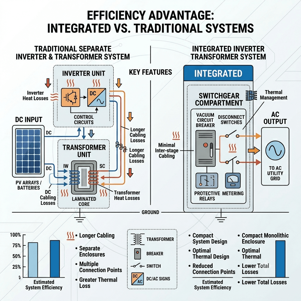
Unlike conventional setups where inverters and transformers are installed separately with long low-voltage cables connecting them, the Integrated Inverter Transformer minimizes the distance between conversion and transformation stages. This compact architecture is what drives the efficiency gains.
The design is often described as a “prefabricated substation” or “PV inverter-booster integrated station,” making it highly portable and quick to deploy in remote or space-constrained locations.
3.The Evolution from Traditional Designs to Integrated Inverter Transformer Solutions
Traditional PV power stations typically use a distributed architecture: multiple inverters located near the arrays feed low-voltage AC power through lengthy cables to a separate step-up transformer substation. While functional, this approach introduces several inefficiencies:
- Higher cabling losses due to long low-voltage runs.
- Increased balance-of-system (BOS) costs.
- Greater footprint and civil works requirements.
- More complex installation, commissioning, and maintenance.
Der Integrated Inverter Transformer represents the next evolution. Manufacturers have leveraged advances in power electronics, transformer miniaturization, and thermal management to combine these functions without compromising performance. This integration has been particularly accelerated by the rise of high-power central inverters (3 MW+) and the demand for modular, plug-and-play solutions in large-scale solar farms.
Today, leading box-type inverter-booster systems support voltages up to 35 kV or higher and power ratings from several hundred kW to multi-MW per unit, making them suitable for both ground-mounted utility plants and large C&I rooftops.
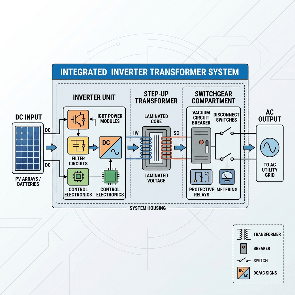
4.Technical Principles: How Transformer + Inverter Integration Works
The magic of the Integrated Inverter Transformer lies in its optimized power flow and minimized intermediate losses. The Integrated Inverter Transformer design complies with international safety standards such as IEC 62109 for power converters in photovoltaic systems.
Power Conversion Process
- DC Input Stage: Solar strings feed DC power (typically 1000–1500 V) into the inverter modules.
- Inversion: Advanced IGBT or SiC-based inverters convert DC to low-voltage AC with efficiencies often exceeding 98.5%.
- Direct Integration to Transformer: The low-voltage AC output connects directly (or via very short busbars) to the primary winding of the step-up transformer.
- Voltage Boost: The transformer raises the voltage to medium levels, reducing current and thereby minimizing I²R losses.
- Output to Grid: Medium-voltage AC is fed directly into the collection system or substation.
This “inverter-to-transformer” direct coupling is a core feature of the Integrated Inverter Transformer. By eliminating long low-voltage cable runs (which can account for 1–3% losses in traditional plants), the system achieves superior end-to-end efficiency.
Advanced Design Features
- Compact Layout: Optimized electromagnetic and thermal modeling allows tight integration while maintaining safety clearances.
- Efficient Cooling: Forced-air, hybrid, or liquid cooling systems maintain optimal operating temperatures even in harsh desert or high-altitude environments.
- Harmonic Mitigation: Built-in filters and transformer design reduce harmonics, improving power quality.
- Smart Controls: Real-time MPPT (Maximum Power Point Tracking), anti-islanding protection, and grid-support functions (reactive power, fault ride-through).
These technical innovations make the box-type inverter-booster integrated machine not just a space-saver but a performance enhancer.
5.Key Advantages: How Integrated Inverter Transformer Technology Boosts PV Plant Efficiency
The primary benefit of adopting an Integrated Inverter Transformer is a measurable increase in overall PV plant efficiency and energy yield. Studies from the U.S. Department of Energy highlight how advanced inverter technologies contribute to higher overall PV plant efficiency and grid stability.
1. Reduced Energy Losses
Long low-voltage cables in traditional systems cause significant resistive losses. Integration cuts these dramatically — often by 50–70%. Combined with high-efficiency components, total system efficiency can improve by 1.5–3 percentage points or more.
2. Higher Energy Yield and Lower LCOE
Even a 1% efficiency gain across a 100 MW plant can translate into millions of additional kWh generated annually. This directly lowers the LCOE, improving project IRR and bankability.
3. Smaller Footprint and Lower BOS Costs
The prefabricated design reduces civil engineering, foundation work, and land usage. Installation time can be cut by 40–60% compared to building separate inverter houses and transformer stations.
4. Enhanced Reliability and Lower O&M Costs
Factory integration and testing minimize on-site errors. Robust enclosures (IP54/IP65 rating) protect against dust, moisture, and extreme temperatures. Integrated monitoring enables predictive maintenance, reducing unplanned downtime.
5. Improved Grid Compliance and Power Quality
Tighter integration allows faster response to grid signals and better harmonic control, ensuring compliance with stringent grid codes.
6.Performance Comparison: Integrated Inverter Transformer vs. Traditional Separate Systems
Here is a detailed side-by-side comparison:
| Parameter | Traditional Separate System | Integrated Inverter Transformer | Improvement |
|---|---|---|---|
| System Efficiency | 96.5–97.5% | 98–99%+ | +1–2.5% |
| Low-Voltage Cabling Losses | 1.5–3% | <0.5% | 60–80% reduction |
| Installation Time | 4–8 weeks per MW block | 1–2 weeks per MW block | 50–70% faster |
| Footprint | Larger (separate pads) | 30–50% smaller | Significant |
| Annual Energy Yield (100 MW plant) | Baseline | +1.5–3% | +1.5–3 GWh |
| LCOE Impact | Higher | 3–8% lower | Major savings |
| Maintenance Access | More complex | Centralized, easier | Lower O&M cost |
| Reliability (MTBF) | Standard | Higher due to factory testing | Improved |
Table 1: Performance Comparison of Integrated Inverter Transformer vs. Traditional Designs
These figures are based on industry benchmarks and real project data from various global installations. Research by the National Renewable Energy Laboratory (NREL) shows that reducing balance-of-system losses through integrated designs can significantly improve long-term energy yield
7.Real-World Case Studies and Quantifiable Results
Case Study 1: 150 MW Utility-Scale Plant in Northwest China A developer replaced traditional inverters + separate transformers with a fleet of box-type inverter-booster integrated machines. Results after one year of operation:
- Overall plant performance ratio (PR) increased from 82% to 85.6%.
- Annual generation exceeded forecasts by 2.8%.
- Installation completed 45 days ahead of schedule.
- BOS cost savings of approximately 8%.
Case Study 2: 50 MW C&I Project in Southeast Asia In a space-constrained industrial park, the Integrated Inverter Transformer solution allowed full deployment with minimal land use. The system demonstrated excellent high-temperature performance, with inverter availability above 99.5% and transformer losses well below design values.
These examples illustrate how the Integrated Inverter Transformer delivers tangible returns across different climates and project scales.
8.Selection Guide: Choosing the Right Integrated Inverter Transformer for Your PV Project
When selecting an All-in-One Inverter Transformer, consider the following factors:
- Power Rating and Scalability: Match unit size to array blocks (e.g., 2.5 MW, 5 MW, or higher).
- Voltage Levels: Input DC voltage range and output MV level must align with grid requirements.
- Environmental Ratings: IP degree, temperature range (-40°C to +55°C typical), and corrosion protection.
- Grid Code Compliance: Ensure support for local requirements (e.g., low/high voltage ride-through, frequency response).
- Monitoring and Integration: Compatibility with existing SCADA or third-party platforms.
- Warranty and Service: Look for comprehensive warranties (5–10 years standard, extendable) and local support.
Working with experienced manufacturers who provide full technical support and customization is recommended for optimal results. For detailed best practices on photovoltaic system operation and maintenance, refer to NREL’s comprehensive guide on PV system performance.
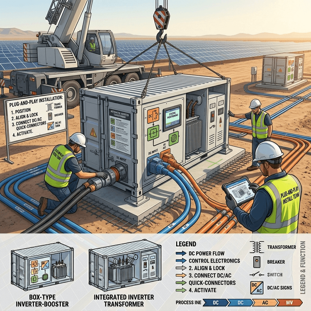
9.Installation, Maintenance, and Best Practices
Installation Advantages The prefabricated nature allows “plug-and-play” deployment. Units are typically transported by truck or ship, lifted into position, and connected to DC inputs and MV outputs with minimal on-site work.
Maintenance Best Practices
- Schedule quarterly visual and thermal inspections.
- Leverage built-in diagnostic tools for remote monitoring.
- Keep cooling systems clean in dusty environments.
- Follow manufacturer-recommended firmware updates for performance optimization.
Properly maintained box-type inverter-booster systems routinely achieve availability rates exceeding 99%.
10.Conclusion: Why Integrated Inverter Transformer Solutions Are the Future of Solar Power Plants
Der Integrated Inverter Transformer represents a significant advancement in PV system design. By combining inverter and transformer functions into a single, efficient Box-Type Inverter-Booster Integrated Machine, developers can achieve higher energy yields, lower costs, faster deployment, and improved reliability.
As the solar industry continues its push toward lower LCOE and higher performance, adopting integrated solutions is no longer optional — it is strategic. Projects equipped with this technology are better positioned to compete in auctions, secure financing, and deliver long-term value.
If you are planning a new PV plant or upgrading existing infrastructure, we invite you to explore how an All-in-One Inverter Transformer solution can transform your project economics. Contact our technical team today for a customized efficiency analysis, detailed quotations, or site assessment. Download our whitepaper on PV plant optimization or schedule a consultation to see the difference integration can make.
The future of solar is integrated — and more efficient than ever.