1.Introduction: Why Transformer Oil Containment Is Critical in Modern Projects
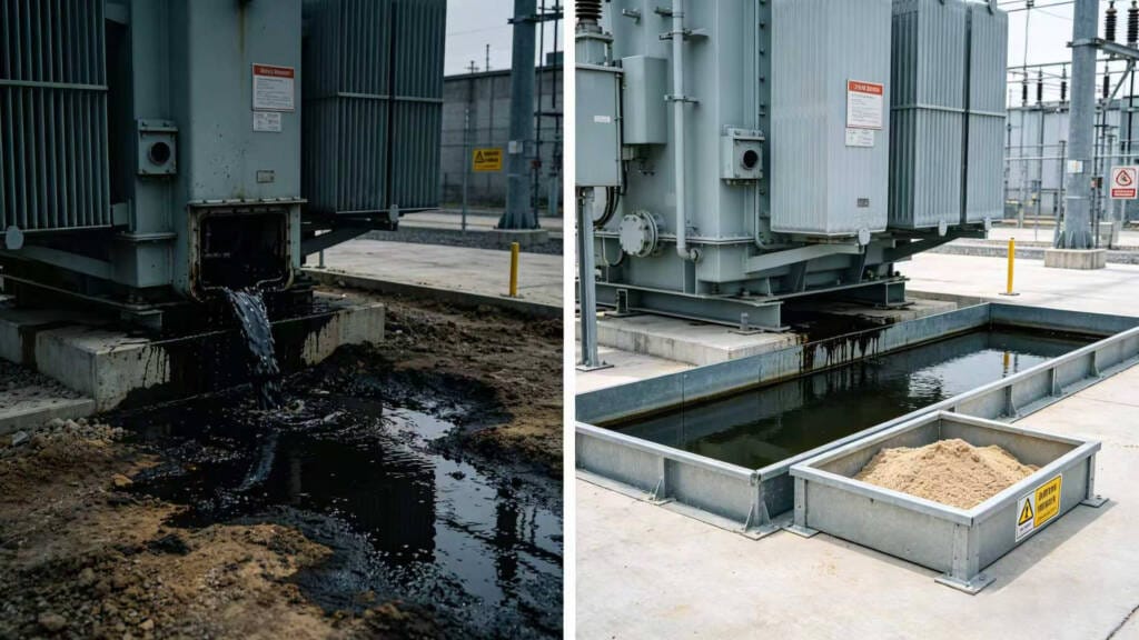
Transformer oil containment has become a central requirement in the design and operation of substations. Oil-filled transformers are the backbone of modern power distribution, but their oil content poses environmental and safety risks. Without proper containment, oil spills can lead to soil contamination, groundwater pollution, and fire hazards. Moreover, oil leaks can result in regulatory fines, project delays, and reputational damage for operators.
Modern engineering recognizes that transformer oil containment should not be an afterthought. Integrating containment systems into substation design ensures compliance with international standards, reduces operational risks, and facilitates long-term maintenance. Proper containment protects the surrounding environment while safeguarding investments in high-voltage and distribution infrastructure.
In this comprehensive guide, we explore the concept, standards, design solutions, calculation methods, and best practices for transformer oil containment, offering a complete reference for engineers, EPC contractors, and utility operators.
جدول المحتويات (TOC)
- Introduction: Why Transformer Oil Containment Is Critical in Modern Projects
- What Is Transformer Oil Containment?
- Environmental Risks of Oil-Filled Transformers
- Common Design Mistakes and Real-World Failure Cases
- International Standards Governing Transformer Oil Containment
- Common Transformer Oil Containment Solutions in Substation Design
- How to Calculate Transformer Oil Containment Capacity
- Transformer Oil Containment for Different Voltage Levels
- Fire Protection Integration with Oil Containment Systems
- Sustainable & Eco-Friendly Transformer Oil Alternatives
- Cost Analysis & ROI: Why Proper Substation Oil Containment Systems Pay Off
- Best Practices for Long-Term Environmental Protection
- Case Study: Oil Containment Design in a 20kV Solar Substation Project
- Conclusion: Why Transformer Oil Containment Should Never Be an Afterthought
- FAQ: Transformer Oil Containment Questions
2.What Is Transformer Oil Containment?
Transformer oil containment refers to engineered systems designed to capture and manage oil leaks from transformers, preventing environmental contamination. These systems serve both safety and regulatory purposes, ensuring that any oil leakage does not reach soil or groundwater.
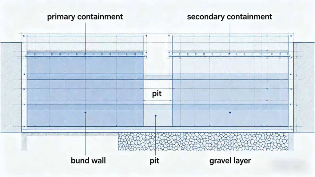
Primary and Secondary Containment
- Primary containment: The transformer tank itself acts as the first line of defense, holding the insulating oil securely.
- Secondary containment: Engineered structures such as oil pits, bund walls, and modular trays capture oil in case the primary system fails.
Key Components of Transformer Oil Containment
| عنصر | غاية | Typical Application |
|---|---|---|
| Oil Pit / Sump | Collects leaked oil | Outdoor substation yards, distribution transformers |
| Bund Wall / Containment Dike | Prevents lateral spread of oil | Large power transformers, high-voltage substations |
| Oil-Water Separator | Separates rainwater and oil | Outdoor installations with drainage systems |
| Modular Containment Trays | Compact containment solution | Box substations, urban areas |
Engineers integrate oil containment systems for transformers into substation layouts to maintain operational safety while ensuring environmental protection compliance.
3.Environmental Risks of Oil-Filled Transformers
Understanding environmental risks is essential for designing effective containment systems.
3.1 Soil Contamination
Transformer oils, especially those containing PCBs or mineral oils, can significantly contaminate soil even in small quantities. Contaminated soil may require expensive remediation and can disrupt surrounding infrastructure. Effective containment prevents these incidents, ensuring long-term site safety.
3.2 Groundwater Pollution
Oil infiltration into soil can reach groundwater, creating environmental and health hazards. Proper Transformer Oil Spill Protection mitigates this risk, protecting local water resources.
3.3 Fire and Explosion Hazards
Oil is flammable. Leaks combined with electrical faults may result in fires or explosions. Integrating fire protection systems with containment measures reduces this risk.
3.4 Regulatory Penalties and Project Delays
Environmental regulations increasingly mandate Transformer Oil Spill Protection. Failure to comply can lead to fines, work stoppages, and legal liabilities. Early adoption of containment systems minimizes these risks and facilitates smooth project execution.
4.Common Design Mistakes and Real-World Failure Cases
Many transformer oil spill containment systems fail due to avoidable design or implementation errors. These mistakes often lead to environmental pollution, hefty fines, project delays, and costly remediation. Understanding common pitfalls in transformer oil containment pit design is essential for engineers and EPC contractors working on substations and solar projects.
Here are the top 5 frequent design mistakes:
- Insufficient Capacity Calculation — Only accounting for transformer oil volume while ignoring rainfall, fire suppression water, or freeboard requirements.
- Inadequate Pit Extension — The containment area does not extend sufficiently beyond the transformer edges (typically 1.5–3 meters as recommended by IEEE 980).
- Improper Lining Materials — Using non-oil-resistant liners or concrete with high permeability (>10^{-6} cm/s), allowing oil to seep into the soil.
- Lack of Effective Oil-Water Separation — No automatic drainage control, causing rainwater accumulation that reduces usable containment volume.
- Poor Long-Term Maintenance Planning — Installing systems without provisions for regular inspection, sensor calibration, or sediment removal.
Real-World Failure Examples (Anonymized): In one Southeast Asian solar farm project, a 20kV transformer’s oil containment pit was sized only to 110% of the oil volume without considering tropical rainfall (50–100 mm in 24 hours). A minor leak combined with heavy rain caused approximately 3,000 liters of oil-water mixture to overflow into nearby waterways. The project faced a 3-month shutdown, remediation costs, and penalties exceeding USD 150,000.
Another 110kV substation retrofit project suffered soil contamination due to unsuitable lining materials. Environmental authorities mandated full soil remediation, adding 8% to the total project budget and delaying financing.
These cases highlight why professional review during the early design phase is critical. At SolarAsia PV, we help clients avoid such risks by conducting thorough substation oil containment systems audits from the conceptual stage.
5.International Standards Governing Transformer Oil Containment
Compliance with international standards ensures both safety and regulatory adherence. Engineers typically reference the following standards:
| معيار | Region | Key Requirement |
|---|---|---|
| SPCC (EPA) | USA | Secondary containment for oil storage in facilities with above-threshold oil volumes |
| IEC 61936-1 | International | Design of high-voltage electrical installations, including oil containment measures |
| IEEE C57 Series | International | Transformer design and oil handling standards |
| NFPA 70 / 850 | USA | Fire safety and electrical protection in substations |
Following these standards helps project teams ensure oil containment system design aligns with best practices while meeting environmental protection requirements.
Concrete oil pits and bund walls are essential for large power transformers. For high-capacity systems like the 2500 kVA Transformer, engineers must calculate containment based on total oil volume. Compliance with SPCC (EPA) guidelines and IEC 61936-1 ensures that the containment system meets environmental regulations. Modular designs are also suitable for urban installations, especially when deploying a Box Substation with limited space.
6.Common Transformer Oil Containment Solutions in Substation Design
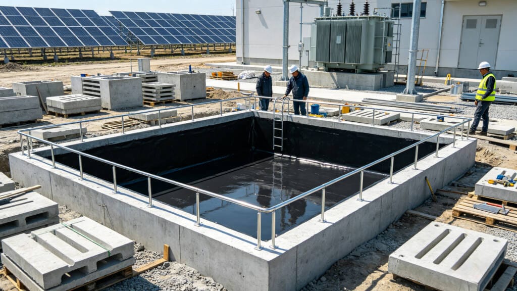
6.1 Concrete Oil Pit / Oil Sump
Concrete oil pits are the most common containment method for oil-filled transformers. They are engineered to hold at least 110% of the transformer’s oil volume and include waterproof liners and sloped floors for drainage.
6.2 Gravel and Fire Barrier Layers
Gravel layers provide passive containment for small leaks and enhance fire protection. They reduce fire propagation and aid in absorbing minor spills, complementing primary containment structures.
6.3 Bund Wall / Containment Dike Systems
Bund walls or containment dikes prevent lateral oil spread in outdoor substations. These structures are typically built around high-capacity transformers, and their height and volume are calculated based on oil volume and regulatory requirements.
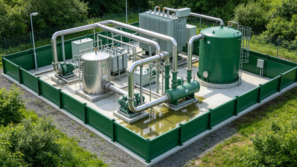
6.4 Oil-Water Separation Systems
Oil-water separators separate rainwater from spilled oil, minimizing maintenance and environmental impact. Automated systems allow for safe disposal and reduce operator intervention.
6.5 Modular Containment for Box Substations
Urban and compact substations often use modular containment trays. These systems fit within the substation footprint, ensuring compliance without occupying excessive space. Modular containment trays are ideal for compact layouts in urban areas, especially when designing a Box Substation with limited space.
7.How to Calculate Transformer Oil Containment Capacity
Correct calculation of containment capacity is essential to meet standards and protect the environment. When calculating containment capacity, engineers should consider the total oil volume of each المحول المنغمس في الزيت to ensure compliance.
Step-by-Step Calculation:
- Determine Total Transformer Oil Volume
Identify the full operational oil capacity of each transformer. - Apply the 110% Containment Rule
V_containment ≥ 1.1 × V_oil
This ensures that containment can handle overfill and small spills. - Include Rainwater Volume
For outdoor installations, add expected rainfall volume to avoid overflow. - Consider Drainage and Separator Systems
If oil-water separators are present, adjust containment volume accordingly.
| نوع المحول | Oil Volume (L) | Containment Volume (L) | ملحوظات |
|---|---|---|---|
| 500 kVA Distribution | 450 | 495 | Small-scale outdoor yard |
| 3150 kVA Power | 4000 | 4400 | Utility substation |
| Box Substation | 1200 | 1320 | Urban modular design |
This approach ensures safe oil pit design and aligns with both SPCC و IEC 61936-1 standards.
8.Transformer Oil Spill Protection for Different Voltage Levels
8.1 Distribution Transformers
- Typically smaller oil pits or bunded areas.
- Often include simple drainage to an oil-water separator.
8.2 20kV / 35kV Substations
- Larger oil pits to accommodate higher oil volumes.
- Fire suppression integration recommended.
8.3 110kV Power Transformers
- High-capacity containment systems mandatory.
- Combination of oil pits, bund walls, and separators.
- Must comply with SPCC and IEC 61936-1.
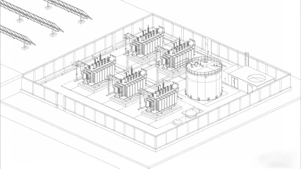
8.4 Utility-Scale Solar Substations
- Modular design is preferred for EPC efficiency.
- Combination of concrete pits, bund walls, and separators.
- Optimized for rapid deployment and maintenance access.
9.Fire Protection Integration with Oil Containment Systems
Integrating fire protection with oil containment enhances substation safety:
- Firewalls and partitions: Prevent fire spread between transformers.
- Foam suppression systems: Rapidly contain oil fires.
- Drainage interlocks: Automatically block oil flow during fire events.
- Explosion hazard mitigation: Reduces risk of catastrophic failure.
Proper integration ensures transformer fire protection systems complement oil containment, protecting personnel and equipment.
10.Sustainable & Eco-Friendly Transformer Oil Alternatives
Modern engineering increasingly favors eco-friendly insulating oils:
- Natural ester fluids (e.g., FR3®) provide high fire points and biodegradability.
- Biodegradable oils reduce soil and water contamination risk.
- Compatibility: Alternative fluids integrate with existing containment systems without modifications.
These alternatives support environmental compliance while maintaining operational reliability.
11.Cost Analysis & ROI: Why Proper Substation Oil Containment Systems Pay Off
While the upfront investment in a professional transformer oil containment system may appear significant, it delivers strong returns by avoiding expensive spill cleanup, regulatory penalties, and downtime.
- Initial Costs: Concrete pits with liners and oil-water separators typically represent 2–5% of total substation cost. Modular containment trays for box-type substations can reduce installation time and labor by 30–50%.
- Long-Term Savings: A single major oil spill can cost hundreds of thousands of dollars in remediation, fines, and lost revenue. Proper substation oil containment systems also speed up project approvals and improve insurance terms.
- ROI Example: In a 20kV solar substation project, investing an additional USD 80,000 in compliant containment enabled the project to connect to the grid three months earlier, generating extra revenue exceeding USD 250,000 while maintaining a zero-spill record.
Choosing natural ester fluids (such as FR3) in combination with modern containment further reduces long-term environmental liability and insurance premiums. For retrofit projects, modular solutions often provide the highest cost-effectiveness.
12.Best Practices for Long-Term Environmental Protection
- Early-stage planning: Incorporate oil containment during design.
- Regular inspection: Monitor pits, bund walls, and separators.
- Leak detection systems: Sensors provide real-time alerts.
- Maintenance of drainage systems: Ensure separators and pits function correctly.
- EPC coordination: Align contractor and operator activities to maintain compliance.
13.Case Study: Oil Containment Design in a 20kV Solar Substation Project
Project Overview:
- Transformers: 2 × 3150 kVA
- Oil Volume: 4000 L per transformer
- Containment: Concrete oil pits + bund walls + oil-water separator
- Compliance: SPCC, IEC 61936-1, IEEE C57
- Fire Protection: Foam suppression with drainage interlocks
Outcome: Zero spills, regulatory approval, reduced maintenance. Early planning and integrated containment ensured operational safety.
14.Conclusion: Why Transformer Oil Spill Protection Should Never Be an Afterthought
Integrating Transformer Oil Spill Protection early in substation design ensures:
- Compliance with international standards
- Environmental and fire safety
- Reduced financial and operational risk
- EPC efficiency and long-term sustainability
15.FAQ: Transformer Oil Containment Questions
- What is transformer oil containment?
A system designed to safely collect oil leaks from transformers, preventing environmental contamination. - How do you calculate transformer oil containment capacity?
Apply the 110% rule and include rainfall allowance if outdoor. - Is oil containment required for all substations?
Required for high-voltage and outdoor transformers to meet standards. - What standards regulate transformer oil containment?
SPCC, IEC 61936-1, IEEE C57 series, NFPA codes. - How deep should a transformer oil pit be?
Typically 0.6–1.5 m, depending on transformer oil volume and 110% rule. - Do box substations need oil containment systems?
Yes, modular trays or pits ensure compliance and safety.