Introduction
A transformer winding is the core component of every electrical transformer. It is responsible for converting voltage, regulating current, and controlling phase in power systems. Transformer winding types include layer winding, disc winding, helical winding, cylindrical winding, crossover winding, and toroidal winding. Each type is designed to meet specific electrical and mechanical requirements.
Proper transformer winding design ensures high efficiency, reduces losses, and enhances safety. Choosing the right winding material, insulation, and winding configuration is essential for engineers, electricians, and anyone working in power distribution or industrial applications.
This guide covers transformer winding types, winding functions, design considerations, configurations, applications—and some frequently asked questions. By the end, you’ll understand pretty much everything about transformer winding. Or at least enough to pick the right type and design for your application. Hopefully.
👉 Explore our transformer solutions
Table of Contents (TOC)
- What is a Transformer Winding?
- Types of Transformer Windings
- Transformer Winding Configurations
- Functions of Transformer Windings
- Design Considerations for Transformer Winding
- Applications of Different Transformer Windings
- Common Questions About Transformer Windings (FAQ)
- Conclusion
1.What is a Transformer Winding?
Definition and Basic Concept
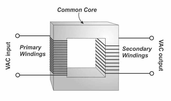
Transformer winding—basically, it’s a set of conductive coils wrapped around a core. Or maybe the core wraps around the coils? No, that’s not right. Anyway. You’ve got the primary winding, which takes energy from the power source—wait, takes energy, or receives? Same thing basically. Then the secondary winding delivers the transformed voltage to the load. The ratio of turns between them? That’s the turns ratio. Determines voltage transformation. Or is it current? Both, I think.
Understanding primary and secondary windings—kind of critical if you want efficient energy transfer. Honestly, you could probably skip understanding it and still get something that works. A poorly designed winding can cause excessive losses, heat, and sometimes the transformer just gives up. Or it works fine but burns out after a year. Hard to tell sometimes. So every transformer, you have to carefully calculate the number of turns, wire thickness, winding arrangement. But honestly, half the time it’s just following a table from the last project.
Materials and Insulation
Transformer windings—copper and aluminum, that’s what you usually see. Copper’s got better conductivity, lasts longer, so it’s good for high-performance stuff. Aluminum’s lighter, cheaper—makes sense for large, medium-voltage transformers where weight’s a concern. Or sometimes they just use whatever’s available that week.
Insulation—critical. Short circuits, overheating, you don’t want those. Common stuff: paper, varnish, enamel, some synthetic materials too. Proper insulation helps the transformer run safely under high voltages. Prevents electrical breakdown. Most of the time, anyway.
2.Types of Transformer Windings
Different transformer winding types—they’re designed for specific applications. Voltage levels, efficiency requirements—that kind of stuff. Or sometimes it’s just whatever the engineer felt like that day.
Layer Winding
Layer winding is one of the most traditional transformer winding types. It consists of coils stacked in layers around the core. This design provides structural stability and handles medium to high voltage efficiently.
Applications: Commonly used in power distribution transformers and medium-voltage industrial transformers.
Advantages:
- Good insulation
- Easy to manufacture
- Reliable performance under high voltage
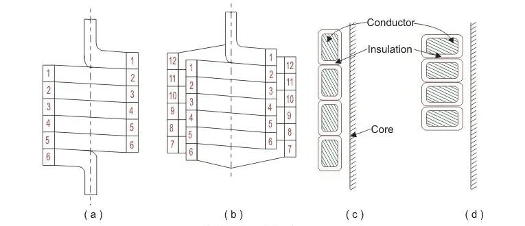
Disc Winding
Disc winding uses flat coils arranged in discs, usually for high-voltage transformers. Each disc is insulated from the others, allowing for effective heat dissipation and reducing leakage flux.
Applications: High-voltage power transformers, industrial heavy-duty transformers.
Advantages:
- High voltage capability
- Excellent cooling performance
- Minimal leakage flux
Table: Layer vs Disc Winding
| Feature | Layer Winding | Disc Winding |
|---|---|---|
| Voltage Rating | Medium to High | High |
| Cooling | Moderate | High |
| Application | Power distribution | High-voltage transformers |
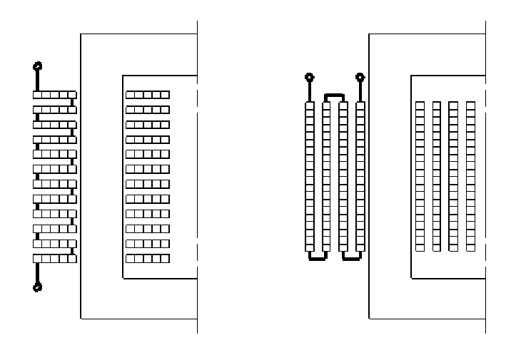
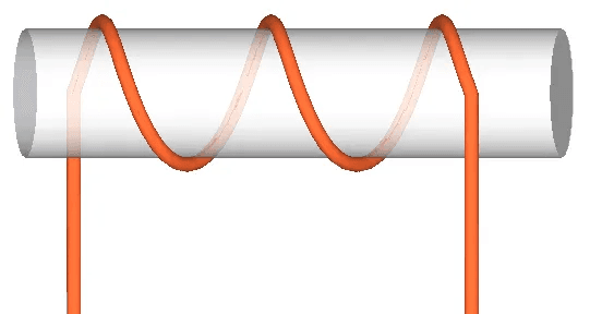
Helical Winding
Helical winding is wound in a spiral around the core. This design distributes current uniformly and reduces resistance. It is widely used in high-frequency transformers and electronic transformers.
Advantages:
- Uniform current distribution
- Simple manufacturing
- Suitable for compact designs
Cylindrical and Crossover Windings
Cylindrical winding is a coil wrapped in a cylindrical shape, commonly used in industrial transformers. Crossover winding arranges coils to reduce leakage flux, improving efficiency.
Applications: Large power transformers, specialized industrial transformers.
Advantages:
- Efficient flux utilization
- Improved transformer performance
- Suitable for high-power applications
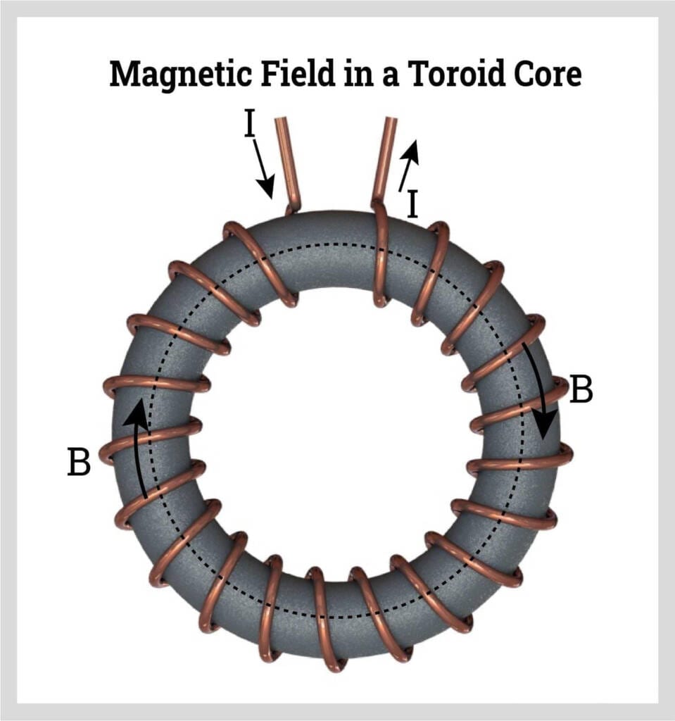
Toroidal Winding
Toroidal winding forms a ring around the core. It minimizes leakage flux, reduces electromagnetic interference, and improves efficiency.
Applications: Compact electronic devices, audio transformers, small power transformers.
Advantages:
- High efficiency
- Compact design
- Low electromagnetic interference
👉 See our power transformers with disc & toroidal windings
3.Transformer Winding Configurations
The winding configuration affects voltage, phase, and efficiency.
Delta Connection
Delta connection connects windings in a triangular shape. It is widely used in three-phase transformers for industrial applications.
Advantages:
- Load balancing
- Fault tolerance
- Stable performance in industrial networks
Wye (Star) Connection
Wye connection connects one end of each winding to a common neutral point. It allows for grounding and voltage adjustments.
Advantages:
- Neutral point for grounding
- Easy voltage control
- Common in power distribution networks
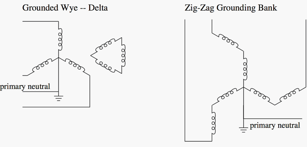
Zig-Zag Connection
Zig-zag connection is a specialized configuration that reduces harmonics and stabilizes current. It is used in systems requiring phase correction.
4.Functions of Transformer Windings
Transformer windings—they do a lot in power systems. Efficiency, safety, reliability—all of that kind of ties back to them. Engineers and electricians who understand how they work? They tend to design and use transformers better. Or at least they don’t mess it up as often.
Voltage Conversion
Main job of a transformer winding? Change the voltage. Input to output, that’s what it does. The turns ratio—that tells you whether it goes up or down. Primary and secondary, they work together to get it right. Most of the time, anyway.
Current Regulation
Transformer windings also handle the current—keeping it in line with what the load needs. Get the winding design right, and it’ll carry the expected current without overheating. Or at least without overheating too much. Losses are another story.
Phase Control
For three-phase systems, windings manage the phase relationship—input to output. Delta, wye, zig-zag—pick the right configuration, and the voltages stay balanced. Pick the wrong one, and things get… interesting. But that’s why you check first.
Efficiency Improvement
Good windings cut down on energy losses. Material, insulation, how you arrange the coils—it all affects resistive losses and leakage flux. Efficient windings save energy, lower operating costs. In theory. Sometimes the savings aren’t as big as you’d hope.
Safety
Transformer windings—they’re what keep things from shorting out or catching fire. Quality insulation, proper winding layout—that’s what protects the transformer, and whatever’s connected to it. Safety’s a big reason engineers spend so much time picking winding types and materials. That, and liability.
5.Design Considerations for Transformer Winding
Designing a transformer winding—there’s a lot that goes into it. Efficiency, safety, performance—each of these gets touched by pretty much every decision you make. Or at least most of them. Engineers kind of have to go through all these elements, piece by piece, if you want something that’s actually going to hold up.
Current and Voltage Ratings
Current and voltage ratings—basically, they tell you how thick the wire needs to be, and how many turns you wind. Higher voltage? More insulation, obviously. Higher current—that’s when you go thicker on the conductor. Get these right, and you avoid overheating. Or most of it, anyway.
Material Selection
Transformer windings—copper or aluminum, usually. Copper’s got the better conductivity, lasts longer too. Aluminum’s lighter, cheaper, so it’s really about what the application needs. Or budget. Or sometimes just what’s in stock.
Insulation Type
Insulation—that’s what keeps the windings from shorting out, or melting down. Paper, varnish, enamel, some synthetic stuff these days. Pick the right one, and the transformer will run fine for years. Unless something else fails first.
Turns Ratio
Turns ratio—primary to secondary—that’s how you actually get the voltage transformation. Get it right, and the output voltage lines up with what the system expects. Mess it up, and you’ll get voltage instability. Or equipment damage.
Cooling and Heat Dissipation
Transformers get hot—that’s just what they do. So you need cooling, air-cooled or oil-cooled usually. Good heat dissipation keeps things from overheating, cuts down losses, helps the transformer last longer. In theory. Assuming nothing else goes wrong.
Manufacturing Complexity and Cost
Winding design—simpler designs cost less to make. More complex ones might give you better efficiency, better insulation. But it’s always a trade-off. Cost, efficiency, reliability—you pick two. Or try to pick all three and hope for the best.
Compliance with Standards
Transformers have to meet international standards—IEEE Transformer Standards, IEC 60076, those kinds of things. Follow them, and you get safety, reliability, and people will actually accept your transformer globally. Skip them, and… well, you probably shouldn’t skip them.
Application Requirements
The winding’s design really depends on where it’s going. High-voltage power transformers, industrial stuff, small electronic transformers—each one’s a little different. Engineers pick the winding type, material, insulation based on what it’s actually going to be used for. Or at least they should.
👉 Contact our engineers for professional transformer design
6.Applications of Different Transformer Windings
Transformer winding types are applied in:
- Distribution transformers – residential and commercial power.
- Industrial power transformers – high-voltage and high-power applications.
- Electronic transformers – toroidal and helical winding for devices.
- Specialized transformers – crossover winding for large power systems.
👉 Browse our full range of transformers
7.Common Questions About Transformer Windings (FAQ)
Q1: What is the difference between primary and secondary transformer winding?
A1: The primary winding receives the input voltage from the power source, while the secondary winding delivers the transformed voltage to the load. The turns ratio between the primary and secondary winding determines the voltage conversion. Choosing the right winding type and material ensures efficient energy transfer.
Q2: Which is better, copper or aluminum for transformer winding?
A2: Copper winding has higher conductivity and better durability, making it suitable for high-performance transformers. Aluminum winding is lighter and cost-effective, ideal for medium to large transformers where weight matters. The choice depends on efficiency, budget, and application requirements.
Q3: How do winding configurations affect transformer performance?
A3: The winding configuration, such as delta, wye (star), or zig-zag, affects voltage, phase relationship, and fault tolerance. Delta connections provide load balancing, Wye connections offer a neutral point for grounding, and Zig-Zag reduces harmonics. Correct configuration improves transformer efficiency and stability.
Q4: What are the best types of transformer winding for high-voltage applications?
A4: Disc winding and layer winding are commonly used in high-voltage transformers due to their excellent insulation and heat dissipation. Toroidal winding can also be used in specialized applications requiring low leakage flux and compact design.
Q5: How can transformer winding losses be minimized?
A5: Losses in transformer winding can be reduced by using high-quality copper or aluminum, proper insulation, correct turns ratio, and optimized winding design. Adequate cooling and spacing also help reduce heat losses, ensuring long-term efficiency.
Q6: Can transformer winding types be mixed in one transformer?
A6: Yes, some transformers use a combination of layer, disc, and helical windings to balance insulation, efficiency, and manufacturing ease. Designers select the type based on voltage, current, and application requirements.
Q7: Why is insulation important in transformer winding?
A7: Insulation, such as paper, varnish, or enamel, prevents short circuits and overheating. Proper insulation ensures the transformer winding operates safely under high voltage and improves lifespan.
👉 Get expert help for your transformer project
8.Conclusion
Transformer winding—honestly, it’s the core of any transformer. Choose the right winding type, materials, insulation, and configuration—and you’re basically set for high efficiency, reliability, and safety. There’s layer, disc, helical, cylindrical, crossover—oh, and toroidal windings. Each one has its own thing, depends on the application.