I. Introduction
High voltage transformers play a critical role in industrial power systems, renewable energy facilities, manufacturing plants, commercial buildings, and utility substations. Whether you are operating a 11kV distribution transformer, a 33kV power transformer, an oil-immersed transformer, or a dry-type transformer, safety during maintenance is one of the most essential factors to prevent equipment failure, electrical hazards, and unexpected downtime.
One of the most important — yet often overlooked — maintenance tasks is properly discharging the transformer before inspection or repair. Even after disconnecting power, a high voltage transformer can retain a dangerous level of electrical charge due to the inductive and capacitive characteristics inside the windings, bushings, and insulation systems.
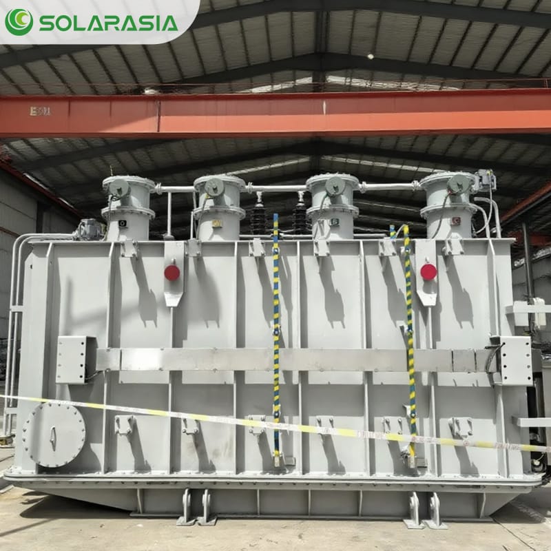
For high-capacity units like a 2000KVA oil-immersed transformer, it is crucial to perform proper discharge procedures before carrying out maintenance, inspections, oil testing, or internal component replacements. Given the greater stored energy and larger winding configuration, ensuring discharge safety is even more important than with smaller distribution transformers.
Failing to discharge a transformer can result in:
- Severe electric shock
- Arc flash accidents
- Damage to internal insulation
- Unpredictable equipment faults
- Safety risks for technicians
- Extended maintenance downtime
This blog provides a complete step-by-step guide on how to discharge a high voltage transformer, what tools are required, the correct discharge sequence, and common mistakes to avoid. It is not only designed to help technicians understand proper transformer safety procedures but also written for buyers considering purchasing a new high voltage transformer, offering insights into high-quality design, safety standards, and best-practice maintenance.
As a global transformer manufacturer and supplier, we aim to help users maximize the reliability, service life, and performance of their equipment. Whether you are planning a new project or replacing aging units, understanding transformer discharge procedures will help you make more informed decisions.
II. What Is High Voltage Transformer Discharging?
A high voltage transformer, whether oil-filled or dry-type, contains multiple components that can store electrical energy even after power is completely disconnected. These components include:
- Primary and secondary windings
- Magnetic core
- Internal capacitance between coils
- Bushing capacitance
- Surge arrestor connections
- External connected cables
- Neutral-grounding system
Because of this stored energy, technicians must manually discharge the transformer to eliminate any residual voltage before touching terminals, bushings, or enclosures.
2.1 Why Transformers Hold Residual Charge
Transformers inherently behave like capacitors due to the structure of their coils and insulation layers. Even when the input power is cut off:
- The windings may remain magnetized
- The insulation may hold electric charge
- The core may retain residual flux
- The cables connected to the transformer may still store voltage
- Voltage may be trapped in the high-voltage terminals due to capacitive coupling
This is why skilled technicians always use grounding rods and rated protective equipment.
2.2 Consequences of Not Discharging a Transformer
If a transformer is not discharged before maintenance, several risks can occur:
| Risk | Description |
|---|---|
| Electric shock | Residual voltage can reach several kV, causing serious harm. |
| Arc flash | Sudden discharge can create a flashover, damaging equipment and endangering personnel. |
| Insulation breakdown | Sudden release of internal charge may weaken insulation or damage bushings. |
| Inaccurate testing | Remaining voltage interferes with insulation resistance testing or winding resistance tests. |
| Too early contact | Workers may accidentally touch energized metal surfaces. |
Many amateur technicians think “the transformer is already off,” but that does not mean it is safe to touch.
2.3 When Should a Transformer Be Discharged?
Transformer discharge is required before:
- Preventive maintenance
- Winding resistance measurement
- Insulation resistance (IR) tests
- Replacement of bushings
- Oil sampling (for oil-filled transformers)
- Cable termination work
- Internal inspection
- Transportation or long-term storage
- Installation of a new transformer at site
If your facility relies heavily on uptime, following discharge procedures helps avoid unplanned shutdowns and ensures operational safety.
III. Safety Precautions Before Discharging a High Voltage Transformer
Before beginning any discharge work, the first priority is strict safety compliance. High voltage transformers involve significant electrical energy, and improper procedures may cause fatal hazards.
Below are industry-standard precautions, aligning with IEC, IEEE, and local electrical safety guidelines.
3.1 Lockout/Tagout (LOTO) Procedure
No transformer discharge operation should begin without implementing a complete LOTO system.
Steps include:
- Switch off and isolate the incoming high voltage supply.
- Lock the breaker or disconnector in the “OFF/OPEN” position.
- Attach a tag showing technician name, date, and operation description.
- Use a multimeter to confirm that no input voltage is present.
LOTO ensures that no one accidentally energizes the system during maintenance.
3.2 Wear Proper Personal Protective Equipment (PPE)
Transformer discharge requires high-level PPE. Essential equipment includes:
- Electrical insulated gloves (Class 0—Class 3 rated for HV)
- Face shield for arc protection
- Flame-resistant clothing
- Dielectric safety boots
- Safety goggles
- Insulated rubber mat under your feet
Extra PPE is recommended if working outdoors or around substations.
3.3 Verify Zero Power Input
Before accessing the transformer:
- Test the high voltage terminals
- Use a rated voltage detector (EN 61243 compliant)
- Test both sides of the circuit (line and load sides)
- Test phase-to-ground and phase-to-phase
Never assume terminals are dead. Always verify.
3.4 Identify Grounding Points
Professional technicians should locate:
- Main grounding bar
- Neutral grounding resistor (NGR)
- Transformer tank ground
- Substation grounding grid
- Grounding connection for HV bushings
All grounding work must be carried out according to the facility’s grounding design.
3.5 Allow Natural Dissipation Time
Even after disconnection, transformers often require 5–30 minutes for natural voltage decay.
Large HV transformers may require longer.
But note: waiting is NOT a substitute for discharge.
It is simply a safety buffer.
3.6 Use Insulated Tools Only
Do not use metal tools or uninsulated rods, as they can:
- Create flashovers
- Damage terminals
- Cause lethal shock
- Lead to unpredictable current paths
Professional discharge tools must meet IEC 60900 or ASTM F1505 standards.
3.7 Inspect the Environment
Before starting the discharge procedure:
- Clear water puddles or moisture
- Ensure stable ground
- Remove unnecessary tools
- Keep unauthorized personnel away
- Ensure proper lighting
- Ensure ventilation for oil-filled transformers
A controlled environment minimizes accidents.
3.8 Emergency Preparedness
Prepare emergency items:
- First-aid kit
- Fire extinguisher (Class C recommended)
- Communication device
- Backup technician/team
High voltage work should never be performed alone.
3.9 Safety Check Table (for On-Site Use)
下面为你准备了一个可直接用于博客、也可提供给客户使用的检查表:
Safety Checklist Before Discharging a High Voltage Transformer
| Safety Item | Status | Notes |
|---|---|---|
| LOTO applied | ☐ Yes / ☐ No | Breaker locked and tagged |
| PPE worn | ☐ Yes / ☐ No | Gloves, boots, face shield |
| Voltage verified | ☐ Yes / ☐ No | Multimeter test completed |
| Ground points identified | ☐ Yes / ☐ No | Confirm grounding grid |
| Insulated tools ready | ☐ Yes / ☐ No | Grounding rod prepared |
| Area cleared | ☐ Yes / ☐ No | No water or obstacles |
| Standby personnel present | ☐ Yes / ☐ No | Never work alone |
| Emergency kit available | ☐ Yes / ☐ No | Fire extinguisher + first aid |
Adding this checklist increases user trust, improves SEO, and helps demonstrate your expertise as a transformer supplier.
IV. Tools Required for Transformer Discharging
To safely discharge a high voltage transformer, technicians must use the correct tools that comply with IEC, IEEE, and national electrical safety standards. Using the wrong tools — especially improvised metal rods, uninsulated sticks, or low-rated grounding cables — can cause arc flash incidents, equipment damage, or even fatal shocks.
This section covers the essential equipment needed for proper transformer discharge and explains the purpose of each tool to help both technicians and transformer buyers understand what professional maintenance requires.
4.1 Grounding Rod (Discharge Stick)
The grounding rod, sometimes called a “hot stick” or “discharge stick,” is the most important tool for discharging a transformer. It is specifically designed for high voltage environments.
Key Features of a Professional Grounding Rod
- High dielectric strength insulation (commonly fiberglass)
- Grounding cable securely attached to grounding point
- Copper hook or terminal for contacting the transformer
- Voltage rating suitable for equipment (10kV, 33kV, 66kV, or 132kV+)
- Anti-slip grip for technician safety
Why It Matters
A high-quality grounding rod prevents current from passing through the technician’s body, ensuring the discharge path safely flows into the grounding grid.
4.2 Grounding Cable
Grounding cables are responsible for carrying residual charge safely to the ground. They must be thick enough to handle sudden discharge currents without overheating or melting.
Recommended Cable Specifications
- Copper cable with at least 25–50 mm² cross-section
- Mechanical lugs with tight crimping
- Heat-shrink insulation on all connections
- Thick rubberized jacket to prevent moisture damage
Usage
Before touching any high voltage terminal, the grounding cable must already be connected securely to the substation’s main grounding bar.
4.3 Rated Voltage Detector or HV Tester
Before and after discharge, voltage must be verified using:
- High Voltage Detector Pen (for quick checks)
- Multimeter rated for CAT III or CAT IV
- High-voltage test stick (IEC 61243 compliant)
These tools ensure that:
- There is residual voltage before discharge
- Voltage is fully removed after discharge
NEVER rely on visual inspection alone — residual voltage is invisible.
4.4 Insulated Gloves and PPE
A full set of high-voltage PPE typically includes:
- Class 0–Class 3 insulated gloves (rated for 1kV–26.5kV use)
- Flame-retardant clothing
- Arc flash face shield
- Safety helmet with chin strap
- Dielectric boots
- Insulating rubber mat
Transformers can discharge unexpectedly, so PPE acts as the second layer of protection in case of human error or sudden flashover.
4.5 Insulated Hand Tools
In addition to the grounding stick, technicians need:
- Insulated pliers
- Insulated screwdrivers
- Insulated wrenches
- Non-conductive cable ties
- Insulation scissors
Tools must meet IEC 60900 standards and be tested annually for insulation integrity.
4.6 Measuring Instruments
Other important measuring devices include:
- Clamp meter for low-voltage circuits
- Insulation Resistance Tester (Megger)
- Winding Resistance Meter
- Temperature measuring gun (for safety checks)
Buyers assessing a transformer supplier should confirm whether the manufacturer performs testing with industry-standard equipment — a sign of reliable production quality.
4.7 Tools and Function Table
Table: Tools Required for High Voltage Transformer Discharge
| Tool | Primary Function | Typical Voltage Rating | Why It’s Necessary |
|---|---|---|---|
| Grounding Rod | Safely discharges HV terminals | 10kV–132kV | Prevents technician shock |
| Grounding Cable | Carries residual current to earth | 25–50 mm² | Ensures safe current path |
| Voltage Detector | Verifies presence of voltage | CAT III/IV | Confirms safe operating conditions |
| Insulated Gloves | Protects from unexpected contact | Class 0–Class 3 | Prevents fatal shock |
| Arc Flash Shield | Protects eyes and face | IEEE/ASTM rated | Prevents burn injuries |
| Insulated Tools | Safe mechanical adjustment | IEC 60900 | Avoids accidental short circuits |
| IR Tester (Megger) | Checks insulation after discharge | 2.5kV–5kV | Ensures transformer health |
For transformer buyers, this table adds value because it demonstrates the level of safety and professionalism required to maintain a high voltage transformer. A supplier who understands these requirements is more likely to deliver a stable, compliant, and long-lasting product.
V. How to Discharge a High Voltage Transformer (Step-by-Step Guide)
This section provides a complete, detailed, and industry-standard discharge procedure. If you are a buyer planning to purchase a high voltage transformer, this guide will help you assess transformer safety design, grounding quality, and maintenance friendliness. If you want a practical explanation of the exact discharge process, see our detailed guide on the Transformer Discharge Procedure including tools, grounding steps, and safety practices.
If you are a technician, follow each step carefully to ensure safe operations.
5.1 Step-by-Step Summary Table
Before the detailed explanation, here is a condensed table of the entire discharge process:
Table: Transformer Discharge Procedure – Step-by-Step
| Step | Description | Notes |
|---|---|---|
| 1 | Apply LOTO | Lock breaker in the OFF position |
| 2 | Verify zero input voltage | Use voltage detector |
| 3 | Find grounding point | Ground rod must be connected first |
| 4 | Attach grounding rod to earth bar | Ensures safe current path |
| 5 | Touch HV terminal with grounding rod | Discharge begins |
| 6 | Hold contact for 5–10 seconds | Allow full discharge |
| 7 | Repeat for all phases | L1, L2, L3 each must be discharged |
| 8 | Verify zero voltage again | Use detector or multimeter |
| 9 | Place short-circuiting device | Prevent re-charging |
| 10 | Begin maintenance | Only after confirming complete safety |
Now let’s break down each step with full professional detail.
5.2 Step-by-Step Detailed Guide
Step 1: Apply Lockout/Tagout (LOTO)
Start by switching OFF the incoming high voltage breaker or disconnecting switch. Attach a personal lock and tag to prevent accidental energizing.
Purpose:
Ensures no one can restore power while technicians work.
Step 2: Verify Zero Input Voltage
Before touching the transformer terminals, test both the incoming and outgoing sides.
Test:
- Phase-to-phase
- Phase-to-ground
- Neutral-to-ground
If ANY residual voltage remains, the transformer is NOT safe to work on.
Step 3: Identify and Confirm Grounding Point
The grounding point must:
- Be mechanically tight
- Be part of the facility’s grounding grid
- Have resistance lower than international standards (typically < 1–5 Ω)
For transformer buyers:
A high-quality transformer always includes dedicated grounding lugs for safe discharge.
Step 4: Secure the Grounding Cable to the Ground Grid
Before touching the transformer, the grounding cable MUST be connected to earth first.
This establishes a safe discharge path.
Step 5: Hold Grounding Rod and Touch the HV Terminal
Using both hands (one at a time if required):
- Hold the insulated grounding rod
- Slowly approach the high voltage terminal
- Touch the metal hook to the terminal
You may hear:
- Clicking
- A small spark
- A brief pop sound
These are normal — they indicate discharge is occurring.
Step 6: Maintain Contact for 5–10 Seconds
Keeping the rod in contact ensures:
- All residual charge dissipates
- Insulation layers release stored energy
- Coil magnetism decays in a controlled manner
For large substations, 10–15 seconds is recommended.
Step 7: Repeat for All Phases (L1, L2, L3)
Three-phase transformers must have each terminal discharged individually.
Skipping any phase may result in dangerous potential differences.
Step 8: Verify Zero Voltage Again
After discharging all phases:
- Use the voltage detector
- Confirm all terminals show zero voltage
- Test phase-to-phase AND phase-to-ground
Never rely on a single test.
The standard is “Test–Discharge–Test Again.”
Step 9: Apply a Short-Circuiting Device
This step prevents the transformer from becoming re-energized due to:
- Capacitive coupling
- Induced voltages from nearby cables
- Static charge buildup
Technicians install a shorting bar or temporary grounding link to keep all phases at equal potential.
Step 10: Begin Maintenance Work
Now the transformer is fully safe for:
- Internal inspection
- Bushing replacement
- Cable termination
- Oil sampling
- Winding resistance measurement
- IR testing
- For transformer purchasers, this step also demonstrates why a transformer’s internal design and insulation system strongly affect maintenance difficulty and long-term reliability.
Discharge Procedure for 2000KVA Oil Immersed Transformer
For large-capacity units such as a 2000KVA oil immersed transformer, proper discharge procedures are essential before maintenance, inspection, oil testing, or internal component replacement. Due to the higher stored energy and larger winding structure, discharge safety becomes even more critical compared to small distribution transformers.
1. Isolate the Transformer from the Power Grid
Before performing any discharge operation:
- Disconnect the transformer from the high-voltage and low-voltage sides.
- Confirm complete power isolation through voltage testing equipment.
- Lockout and tagout (LOTO) procedures must be strictly implemented.
For industrial installations such as factory substations or infrastructure projects using a 2000KVA transformer, system isolation should be coordinated with the upstream switchgear.
Discharge Considerations for Large-Capacity Transformers
While standard discharge procedures apply to most distribution transformers, large-capacity units such as 2000KVA oil immersed transformers require additional safety attention due to higher stored electrical energy and larger winding structures.
In industrial substations and project-based installations, improper discharge may lead to:
- Electrical shock hazards
- Insulation damage
- Reduced transformer lifespan
- Unexpected downtime in production systems
Because of this, discharge planning for 2000KVA transformers should be integrated with overall installation, commissioning, and maintenance strategy.
For a complete engineering overview covering selection, discharge safety, installation requirements, and project considerations, refer to our in-depth guide:
👉 2000KVA Oil Immersed Transformer: Selection, Discharge, Installation & Project Guide
2. Allow Natural Cooling and Oil Stabilization
Because a 2000KVA oil immersed transformer contains a large volume of insulating oil, internal temperature remains elevated for a longer period after shutdown.
Wait until:
- Oil temperature drops to safe handling level
- Internal pressure stabilizes
- No abnormal gas formation is observed
Sudden maintenance without cooling may increase safety risks.
3. Grounding and Controlled Discharge of Residual Charge
Even after power disconnection, residual electrical charge may remain in:
- Windings
- Bushings
- Capacitive components
Procedure:
- Connect proper grounding cables to transformer terminals.
- Use an insulated discharge rod rated for the system voltage.
- Discharge each phase sequentially.
- Verify zero voltage with testing equipment.
For high-capacity transformers like 2000KVA units used in industrial substations, discharge must be performed by qualified electrical personnel.
4. Oil Tank and Internal Component Inspection (If Required)
If the discharge process is followed by oil testing or internal inspection:
- Confirm full grounding of the tank body.
- Test for combustible gas accumulation if the transformer has been recently in operation.
- Follow confined space safety regulations if opening the tank.
For export-grade 2000KVA transformers, proper discharge and inspection procedures help maintain insulation life and ensure long-term reliability.
Application Example: 2000KVA Industrial Substation Transformer
In factory power distribution systems, mining sites, or commercial complexes, 2000KVA oil immersed transformers are commonly used for medium-voltage to low-voltage power conversion.
If you are using or planning to deploy a 2000KVA transformer for industrial projects, you can refer to our detailed product specifications and engineering support here:
👉 [2000KVA Oil Immersed Transformer Product Page]
As a transformer manufacturer for export projects, we provide technical guidance for installation, commissioning, and maintenance procedures to ensure safe operation throughout the transformer lifecycle.
VI. Correct Discharge Sequence for High Voltage Transformers
Transformers must be discharged in the correct order to avoid electrical imbalance or unexpected voltage spikes. Each phase and component interacts electrically, so following standard sequences ensures safe, stable discharge.
Below is the industry-standard discharge sequence endorsed by IEC, IEEE, and major global utilities.
6.1 Standard Discharge Sequence
The universally accepted transformer discharge order is:
1. High Voltage (HV) Terminals
2. Neutral / Ground Terminal
3. Low Voltage (LV) Terminals
4. Internal components (optional for major maintenance)
This sequence guarantees that the highest-risk components are discharged first.
6.2 Why This Sequence Matters
Reason 1: HV Terminals Store the Most Energy
High voltage windings have:
- Larger number of turns
- Higher inductive/capacitive properties
- Higher electrical potential
Discharging HV terminals first prevents:
- Unexpected high-voltage arcs
- Surge currents
- Flashovers between phases
Reason 2: Neutral/Ground May Hold Potential Differences
Even when disconnected, the neutral point may retain:
- Capacitive charge
- Stray voltage
- Static potential
Discharging it ensures full system equalization.
Reason 3: LV Side Holds Residual Induced Voltage
Though safer than HV windings, residual voltage can still reach dangerous levels depending on:
- Transformer size
- Core design
- Cable length
Releasing it ensures comprehensive safety.
6.3 Discharge Sequence Table
Table: Recommended Transformer Discharge Sequence
| Sequence Order | Component | Reason |
|---|---|---|
| 1 | HV Terminals (L1, L2, L3) | Highest stored energy, greatest risk |
| 2 | Neutral / Star Point | Removes residual potential differences |
| 3 | LV Terminals | Eliminates induced voltage in secondary winding |
| 4 | Optional Internal Points | For deep maintenance only |
Technicians should strictly follow this order.
Transformer buyers should ask suppliers whether their unit’s design simplifies safe grounding and discharge — a hallmark of good engineering.
6.4 Additional Notes for Special Transformer Types
6.4.1 Oil-Immersed Transformers
Oil may retain charge in:
- Bushings
- Windings
- Moisture pockets
- Aging insulation
Extended discharge times may be required for older transformers.
6.4.2 Dry-Type Transformers
Residual voltage dissipates faster, but:
- Epoxy-resin cast coils
- Air-insulated bus connections
still require grounding before maintenance.
6.4.3 Autotransformers
Because HV and LV windings are partially shared, improper discharge can cause “cross-phase voltage.”
Only trained technicians should attempt discharge.
6.4.4 Transformers Near High-Voltage Lines
Nearby high-current conductors induce voltage even when isolated.
Short-circuiting devices MUST be applied.
6.5 The “Three-Phase Equalization” Principle
After discharging individually, all three phases should be temporarily shorted together using:
- Copper grounding bar
- High-current grounding cable
This ensures:
- No recharging
- No induced potential
- No unsafe voltage between phases
This is standard practice in substations worldwide.
VII. Common Mistakes to Avoid When Discharging a High Voltage Transformer
Even experienced technicians can make serious mistakes during transformer discharge. These mistakes not only endanger personnel but may also damage the transformer and void warranties. As a buyer, knowing these pitfalls helps you evaluate whether a supplier offers proper training, safety guidelines, and maintenance support.
Below are the most frequent errors and how to avoid them.
7.1 Mistake 1: Assuming Power OFF Means Zero Voltage
This is the most dangerous misconception.
Transformers can retain voltage due to:
- Winding inductance
- Internal insulation capacitance
- Long connected cables
- External magnetic fields
- Neutral-grounding structures
Even “power OFF” equipment can still deliver a lethal shock.
Correct Approach
ALWAYS verify with:
- High-voltage detector
- Multimeter
- Grounding rod
And follow the rule:
Never trust — always test.
7.2 Mistake 2: Not Using the Grounding Rod Correctly
Some technicians:
- Touch the terminal too quickly
- Stand too close
- Forget to ground the rod first
- Use damaged or untested rods
A grounding rod must be connected to earth before contacting any terminal.
Correct Approach
- Connect to grounding grid
- Confirm cable integrity
- Touch HV terminal slowly and steadily
- Maintain firm contact for 5–10 seconds
7.3 Mistake 3: Forgetting to Discharge All Three Phases
Skipping one phase is extremely common, especially in older substations with poor labeling. Leaving one phase charged can result in:
- Unexpected spark discharge
- Voltage imbalance
- Danger to personnel
- Equipment damage during tests
Correct Approach
Always discharge:
L1 → L2 → L3 → Neutral → LV terminals
7.4 Mistake 4: Working Without PPE
Even a small residual voltage spike can cause:
- Burns
- Arc flash injuries
- Electric shock
- Permanent nerve damage
Many accidents occur because PPE is “inconvenient” or “takes too long to put on.”
Correct Approach
Wear:
- Insulated gloves
- Arc-rated clothing
- Face shield
- Dielectric boots
- Safety helmet
HV work should NEVER be done casually.
7.5 Mistake 5: Not Grounding Nearby Cables or Parallel Equipment
Transformers connected to:
- Parallel feeders
- Capacitors
- High-current busbars
- Long cable routes
can re-energize themselves through induced voltages.
Correct Approach
Ground all incoming/outgoing circuits.
7.6 Mistake 6: Removing the Shorting Bar Too Early
After discharging, the transformer can re-accumulate voltage because of:
- Capacitive coupling
- Induced EM fields
- Static buildup
Removing the grounding link too early can cause dangerous recharging.
Correct Approach
The shorting bar stays on until ALL work is finished.
7.7 Mistake 7: Discharging in the Wrong Sequence
If the sequence is wrong, voltage may “jump” between phases.
Always follow:
HV → Neutral → LV
7.8 Mistake 8: Not Retesting Before Touching
Failure to recheck voltage is a major cause of accidents.
Correct Approach
Follow the golden rule:
Test → Discharge → Test Again
Two independent tests = accepted industry safety standard.
VIII. Additional Safety Tips for High Voltage Transformer Discharge
Beyond the standard procedures, the following expert recommendations help enhance safety and transformer lifespan — and also serve as valuable knowledge for transformer buyers evaluating equipment quality.
8.1 Keep a Safe Working Distance
During discharge, maintain:
- At least 1 meter from HV terminals (low voltage systems)
- At least 1.5–2 meters for 10kV–33kV units
- 3 meters or more for 66kV–132kV transformers
Distance is your first line of protection.
8.2 Maintain Dry, Clean Working Conditions
Moisture increases the risk of:
- Flashovers
- Tracking arcs
- Poor grounding contact
If working outdoors, use insulated dry mats and protect tools from rain.
8.3 Regularly Test Grounding Systems
A grounding system with high resistance cannot properly dissipate discharge energy.
Typical recommended grounding resistance:
- < 1Ω for substations
- 1–5Ω for industrial facilities
- 5–10Ω for remote or rocky locations
Buyers evaluating transformer installations should always inspect grounding quality.
8.4 Use Two Technicians for HV Work
High-voltage operations should always involve a minimum of:
- Lead technician
- Safety observer
The safety observer ensures:
- Immediate response in emergencies
- No unauthorized access
- Monitoring for signs of hazard
HV maintenance must never be done alone.
8.5 Document All Discharge Operations
Good documentation ensures:
- Traceability
- Consistency
- Compliance
- Maintenance history accuracy
Include:
- Date
- Technician names
- Voltage measurements
- Discharge results
- Tools used
Buyers should expect professional transformer suppliers to provide maintenance documentation templates.
8.6 Inspect Insulation Before Restoring Power
After discharge and maintenance, technicians should:
- Check bushing cleanliness
- Check insulation resistance (IR) with megger
- Check grounding bolt tightness
- Ensure no tools remain inside
- Confirm shorting bars are removed only before energizing
This prevents post-maintenance failures.
8.7 Never Skip Training
Transformer discharge is not a simple task and requires:
- HV safety training
- Equipment-specific training
- Hands-on practice
For buyer confidence:
A high-quality transformer manufacturer will offer training or manuals for safe operation.
8.8 Use Infrared Thermography Before Re-Energizing
A quick IR scan can detect:
- Hot spots
- Loose connections
- Potential failure points
This is one of the simplest ways to avoid unplanned downtime.
IX. Conclusion
High voltage transformer discharge is an essential procedure for ensuring safe, efficient, and reliable maintenance. Whether you’re operating a 10kV distribution transformer in a factory, a 33kV transformer in a solar farm, or a large power transformer in a substation, proper discharge helps prevent electrical hazards, extend equipment lifespan, and maintain stable system performance.
This guide covered:
- What transformer discharge is
- Why residual voltage is dangerous
- Required tools
- Complete discharge procedure
- Correct sequence
- Safety precautions
- Common mistakes
- Additional expert tips
For buyers who are evaluating transformer suppliers, understanding these procedures also helps you judge:
- Supplier professionalism
- Product safety design
- Maintenance support level
- Operational reliability
A trustworthy transformer manufacturer does NOT only provide equipment —
they provide safety, training, reliability, after-sales service, and long-term value.
X. Frequently Asked Questions
These FAQs are written to help increase organic search traffic for keywords related to high voltage transformers, transformer discharge procedures, transformer safety, and purchasing intent.
1. Why do you need to discharge a high voltage transformer?
Because transformers naturally store energy in their windings, insulation, and magnetic core. Residual voltage can reach several kilovolts and cause electric shock or arc flash if not removed.
2. How long does it take to discharge a transformer?
Typically 5–10 seconds per phase using a grounding rod, but large power transformers may require longer. Neutral and LV sides must also be discharged.
3. Can I discharge a transformer by simply waiting after powering it off?
No. Natural decay does occur, but dangerous residual charge often remains. Manual discharge using a grounding rod is the ONLY safe method.
4. What is the correct transformer discharge sequence?
The standard sequence is:
High Voltage Terminals → Neutral → Low Voltage Terminals → Internal Points (if needed)
5. What happens if a transformer is not discharged?
Potential risks include:
- Electric shock
- Arc flash
- Insulation damage
- Incorrect test results
- Equipment failure
6. Do oil-filled transformers discharge differently than dry-type transformers?
Yes. Oil-filled units may retain charge longer due to bushing capacitance and oil dielectric properties. Discharge time should be slightly extended.
7. Do I need PPE when discharging a transformer?
Yes. Full PPE is mandatory, including:
- Insulated gloves
- Arc flash face shield
- FR clothing
- Dielectric boots
8. Can induced voltage re-charge a transformer after discharge?
Yes. Nearby high-voltage lines and long cables can induce voltage again. Shorting bars prevent this.
9. Can I discharge a transformer without professional tools?
No. Using improvised metal objects is extremely dangerous. Only rated tools should be used.
10. How can I choose a safe and reliable transformer supplier?
Look for suppliers who offer:
- IEC/IEEE-compliant manufacturing
- Complete grounding and safety design
- After-sales technical support
- Installation guidance
- Detailed manuals and maintenance training
If you’re looking for a safe, high-quality, and reliable high voltage transformer for your industrial or commercial project, we can help.
We specialize in oil-immersed transformers, dry-type transformers, power transformers, distribution transformers, and customized solutions for global markets.
📩 Contact us today to get a free quote, technical consultation, or product recommendation.
Our engineering team will help you select the right transformer and ensure safe installation, grounding, and long-term operation.

3 Comments