1.Introduction: Why the Transformer Core Matters
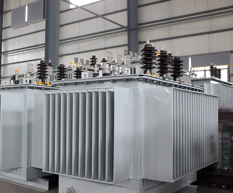
In any electrical power system, the transformer core plays a critical role in determining efficiency, performance, and reliability. Whether used in power transmission, distribution networks, or electronic devices, the core acts as the foundation of magnetic energy transfer.
A well-designed iron core improves magnetic coupling, reduces energy losses, and ensures stable voltage transformation. On the other hand, poor core design can lead to excessive heat, energy waste, and reduced lifespan.
In this complete guide, we will explore everything you need to know about transformer cores, including:
- What a iron core is
- How it works
- Types of transformer cores
- Core materials and their differences
- Construction methods
- Core losses and efficiency
- How to choose the right transformer core
Table of Contents
- Introduction: Why the Transformer Core Matters
- What Is a Transformer Core?
- How Does a Transformer Core Work?
- Types of Transformer Core
- Transformer Core Materials Explained
- Transformer Core Construction
- Transformer Core Losses and Efficiency
- Key Factors in Transformer Core Design
- How to Choose the Right Transformer Core
- Applications of Transformer Core
- Transformer Core vs Winding
- FAQ: Transformer Core
- Conclusion
2.What Is a Transformer Core?
A transformer core is a magnetic structure that provides a controlled path for magnetic flux in a transformer. It works by efficiently guiding magnetic flux in transformers between the primary and secondary windings. By concentrating the magnetic field, the core minimizes energy loss and improves overall efficiency.
Key Functions of a Transformer Core
The transformer core is the central component of a transformer, acting as a magnetic circuit that efficiently transfers energy between windings. Its main role is to provide a low reluctance path for magnetic flux, ensuring maximum energy transfer and minimizing losses. By doing so, it improves magnetic coupling between the primary and secondary windings, reducing leakage flux that can otherwise cause voltage drops or inefficiencies.
Modern cores are designed to reduce eddy currents and stray magnetic flux, enhancing overall transformer energy efficiency. Materials such as laminated silicon steel or amorphous metals help achieve these goals, allowing transformers to operate reliably at high power and frequency. In simple terms, the transformer core is not just a passive element—it is the heart of the magnetic circuit, ensuring efficient, stable, and low-loss performance.
Looking for high-performance transformer cores or complete transformer solutions?
👉 Contact us now for custom design, competitive pricing, and fast global delivery.
3.How Does a Transformer Core Work?
The working principle of a transformer core is based on electromagnetic induction.
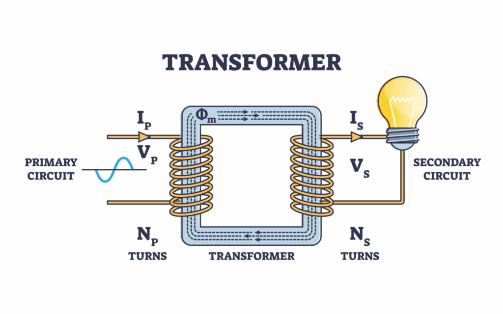
Basic Working Process
The basic working process of a transformer core begins when alternating current (AC) flows through the primary winding. This current produces a time-varying magnetic field, and the transformer’s magnetic core concentrates and guides it. The core acts as a low reluctance path for magnetic flux, ensuring that most of the magnetic energy links efficiently with the secondary winding.
As the magnetic flux passes through the core, it induces a voltage in the secondary winding according to Faraday’s law of electromagnetic induction. This allows energy to transfer from the primary to the secondary winding without any direct electrical connection. By minimizing leakage flux and optimizing magnetic coupling, the transformer core ensures efficient energy transfer with minimal losses, making it the essential component in both power and distribution transformers.
Key Concept: Magnetic Flux
The efficiency of a transformer depends on how effectively the core can carry magnetic flux. Materials with high permeability allow stronger flux with less energy.
4.Types of Transformer Core
Understanding the types of magnetic core is essential for selecting the right design for specific applications. Different core types offer unique advantages in terms of efficiency, magnetic coupling, size, and leakage flux control. The three most common types are core type, shell type, and toroidal transformer cores.
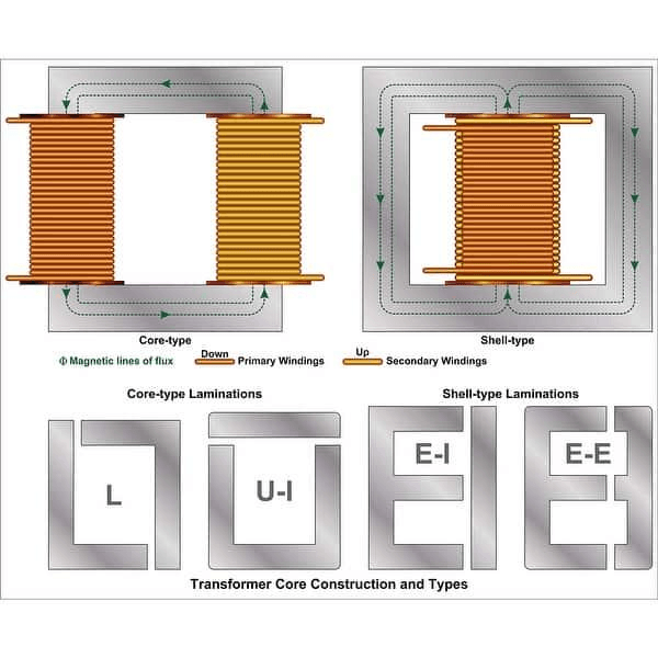
1. Core Type Transformer
In a core type transformer, the primary and secondary windings are placed on separate limbs of a rectangular core. This simple design provides easy cooling and is relatively straightforward to manufacture. It is widely used in power transformers due to its robustness and reliability. Although it may have slightly higher leakage flux compared to shell type designs, its simplicity and cost-effectiveness make it a popular choice for many industrial and utility applications.
2. Shell Type Transformer
The shell type transformer features windings placed on the central limb of a multi-legged core. This design offers better magnetic shielding and reduces leakage flux, resulting in higher energy efficiency. Shell type cores are particularly suitable for applications where voltage regulation, noise reduction, and compact design are critical. They are commonly used in distribution transformers and high-performance industrial equipment.
3. Toroidal Core Transformer
The toroidal magnetic core uses a ring-shaped magnetic core, around which the windings are evenly wound. This compact design provides excellent magnetic coupling, low electromagnetic interference (EMI), and high efficiency. Toroidal transformers are often chosen for precision electronics, medical equipment, and high-frequency applications due to their minimal magnetic leakage and smooth voltage output.
By understanding the advantages and limitations of each core type, engineers can select the magnetic core that best balances efficiency, size, and application requirements.
Comparison of Transformer Core Types
| Core Type | Structure | Efficiency | Cost | Applications |
|---|---|---|---|---|
| Core Type | Two limbs | Medium | Low | Power transformers |
| Shell Type | Central limb | High | Medium | Industrial transformers |
| Toroidal | Circular | Very High | High | Electronics, medical |
Need reliable magnetic circuit core solutions for your project?
👉 Get a free quotation within 24 hours and expert technical support today.
5.Transformer Core Materials Explained
The choice of magnetic core materials is a critical factor that directly affects a transformer’s performance, efficiency, energy losses, and overall cost. Selecting the right core material ensures reliable operation, reduces heat generation, and improves long-term energy efficiency. Different materials are suited for different applications, from power and distribution transformers to high-frequency switching devices.
1. Silicon Steel Core
Silicon steel is the most widely used material in traditional transformers due to its excellent magnetic permeability and relatively low hysteresis loss. It consists of thin laminated sheets of steel coated with an insulating layer to minimize eddy current losses. Silicon steel cores are commonly found in power transformers and distribution transformers because they offer a good balance between performance, cost, and manufacturability. Engineers often choose grain-oriented silicon steel for high-efficiency transformers, as it aligns the magnetic domains to further reduce energy loss.
2. Ferrite Core
Ferrite cores use ceramic-based magnetic materials with high electrical resistance, which significantly reduces eddy current losses and makes them ideal for high-frequency applications. Engineers commonly use ferrite in switching power supplies, inverters, and signal transformers. Although ferrite cores are brittle and cannot handle very high power levels like silicon steel, their low losses at high frequencies make them indispensable in modern electronics.
3. Amorphous Metal Core
Amorphous metal cores are advanced materials with a disordered atomic structure, resulting in extremely low core losses compared to traditional silicon steel. They provide high energy efficiency, making them ideal for energy-saving transformers in commercial and industrial settings. The reduced hysteresis and eddy current losses in amorphous metal cores help minimize heat generation, lower operating costs, and improve transformer lifespan. Despite their higher initial cost, amorphous metal transformers offer significant long-term energy savings, supporting sustainability goals and compliance with efficiency standards.
Material Comparison Table
| Material | Frequency Range | Core Loss | Cost | Application |
|---|---|---|---|---|
| Silicon Steel | Low (50/60Hz) | Medium | Low | Power grid |
| Ferrite | High (kHz–MHz) | Low | Medium | Electronics |
| Amorphous | Low | Very Low | High | Energy-efficient systems |
6.Transformer Core Construction
The magnetic core construction is designed to minimize losses and maximize efficiency.
1.Laminated Core Structure
Most transformer cores are made of thin laminated sheets rather than solid metal.
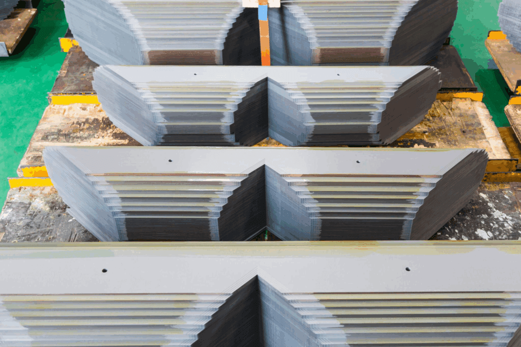
Why Laminated Core?
- Reduces eddy current loss
- Minimizes heat generation
- Improves efficiency
Each lamination is insulated from the others to prevent circulating currents.
2.Core Assembly Methods
- E-I core assembly
- U-I core assembly
- Step-lap core construction
Step-lap design further reduces noise and losses in modern transformers.
3.Winding and Core Relationship
- Concentric winding improves flux linkage
- Sandwich winding reduces leakage
Proper arrangement enhances overall transformer performance.
Custom transformer core design for your specific application
👉 Talk to our engineers and get a tailored solution that fits your exact requirements.
7.Transformer Core Losses and Efficiency
Even when a transformer operates with no load, its magnetic core experiences inherent energy losses known as core losses or iron losses. These losses affect overall efficiency and are primarily composed of hysteresis loss and eddy current loss. Understanding these losses is crucial for engineers aiming to design high-efficiency transformers for power, distribution, or industrial applications.
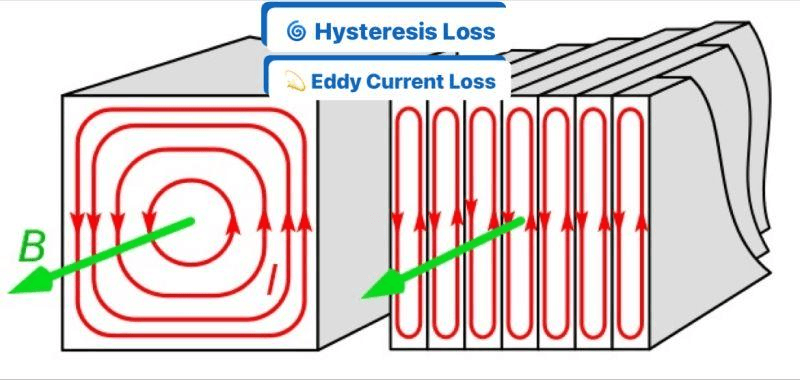
1. Hysteresis Loss
Hysteresis loss occurs due to the repeated magnetization and demagnetization cycles in the magnetic core as alternating current flows through the primary winding. The energy required to realign the magnetic domains in the core material is dissipated as heat. Hysteresis loss depends heavily on the core material properties, such as grain orientation, magnetic permeability, and silicon content in silicon steel. Selecting materials with low hysteresis characteristics helps reduce energy waste, improving the transformer’s overall efficiency and longevity.
2. Eddy Current Loss
Eddy current loss occurs when circulating currents form inside the laminated core as the magnetic flux changes direction. These currents generate unwanted heat and lower transformer efficiency. Engineers minimize eddy current losses by constructing transformer cores from thin laminated sheets of magnetic steel, each separated by an insulating layer. This lamination increases resistance along the sheet planes and effectively restricts circulating currents. This lamination increases the electrical resistance along the plane of the sheets, effectively reducing circulating currents. Advanced materials like amorphous metal or ferrite further reduce eddy currents, especially in high-efficiency or high-frequency transformers.
By controlling both hysteresis and eddy current losses, engineers can significantly enhance transformer efficiency, reduce operating costs, and minimize heat generation. Efficient cores not only save energy but also contribute to longer transformer life and compliance with energy efficiency standards, making material selection and core design essential for any high-performance transformer project.
Core Loss Summary
| Loss Type | Cause | Reduction Method |
|---|---|---|
| Hysteresis | Magnetic reversal | Better material |
| Eddy Current | Induced currents | Laminations |
Key Insight
Core loss is constant and independent of load, making it a critical factor in transformer efficiency.
8.Key Factors in Transformer Core Design
When designing or selecting a laminated core, engineers often refer to international standards such as IEC standards. These standards define testing methods, efficiency benchmarks, and safety requirements to ensure reliable operation across different applications.
A good laminated core design balances multiple engineering factors:
1. Magnetic Flux Density
- Too high → saturation
- Too low → inefficient
2. Material Selection
- Determines losses and performance
3. Operating Frequency
- High frequency requires ferrite
- Low frequency uses silicon steel
4. Temperature Rise
- Excess heat reduces lifespan
5. Core Size and Weight
- Trade-off between efficiency and cost
9.How to Choose the Right Transformer Core
Selecting the right laminated core depends on application requirements.
Step-by-Step Selection Guide
- Determine operating frequency
- Identify power rating
- Evaluate efficiency requirements
- Consider cost constraints
- Check size and installation limits
Example Selection
| Application | Recommended Core |
|---|---|
| Power grid | Silicon steel |
| High-frequency circuit | Ferrite |
| Energy-saving system | Amorphous |
Factory-direct transformer cores with competitive pricing
👉 Request your latest price list and product catalog now.
10.Applications of Transformer Core
For advanced engineering applications, designers may follow published by industry organizations. These resources provide insights into optimization techniques, material innovations, and performance improvements.
Transformer cores are used across multiple industries:
- Power transmission systems
- Distribution transformers
- Renewable energy systems
- Industrial equipment
- Electronic devices
11.Transformer Core vs Winding
| Component | Function |
|---|---|
| Core | Magnetic flux path |
| Winding | Electrical conduction |
Both must be optimized together for best performance.
12.FAQ: Transformer Core
What is iron core made of?
Transformer cores are typically made from silicon steel, ferrite, or amorphous metal depending on application.
Why is iron core laminated?
Lamination reduces eddy current loss and improves efficiency.
What causes core loss in transformers?
Core loss is caused by hysteresis and eddy current effects.
Which core is best for high frequency?
Ferrite cores are best due to low losses at high frequencies.
What is the function of iron core?
It provides a path for magnetic flux and enables efficient energy transfer.
13.Conclusion
The magnetic core is the heart , influencing efficiency, performance, and durability. By understanding core types, materials, construction methods, and losses, engineers and buyers can make informed decisions.