Transformer lossessilently consume 1-2% of global electricity, makingtransformer efficiencya critical factor for both engineers and procurement teams.Core loss in transformer(also callediron loss in transformerorno-load loss in transformer) runs 24/7 whilecopper loss in transformer(load loss in transformer) spikes under heavy industrial loads. Understandingcore loss vs copper loss,stray losses in transformer, anddielectric loss in transformerrevealshow to reduce transformer lossesand optimizetransformer total cost of ownership.
This guide coverstransformer loss calculation,transformer efficiency curveanalysis, andtransformer lifecycle costevaluation—showing whyhigh efficiency transformersandlow loss transformersdeliver superior ROI despite higher upfront costs. You’ll learntransformer procurementstrategies,transformer tender specificationbest practices, and howdistribution transformer lossesdiffer frompower transformer lossesin utilities versus industrial applications.
Fromtransformer coolingandtransformer hot spot temperaturemanagement totransformer overload/transformer underloadimpacts ontransformer loss of life, this resource equips you to specifyenergy efficient transformersthat minimizeno-load vs load lossesand maximize long-term value.
Table of Contents
- Introduction: Why Transformer Losses Matter
- Understanding Transformer Losses and Efficiency
- Main Types of Transformer Losses
- How Transformer Losses Affect Efficiency and Thermal Performance
- From Watts to Dollars: Calculating the Cost of Transformer Losses
- Design Strategies to Reduce Transformer Losses (For Engineers)
- Specification and Purchasing Guide (For Buyers and Procurement Teams)
- Application Examples: Utilities, Industry, and Data Centers
- Practical Checklists for Engineers and Buyers
- FAQs on Transformer Losses and Efficiency
- Key Takeaways and Next Steps
1. Introduction: Why Transformer Losses Matter
Engineers tend to obsess over hot spots and insulation ageing—worried about reliability and where failures might start. Buyers, on the other hand, usually keep their eyes on the purchase price and the delivery schedule. Both are valid concerns, sure. But looking at them separately? That misses the bigger picture.
Engineers tend to focus on hotspots, insulation ageing, and keeping things reliable. Buyers are usually looking at the purchase price and delivery time. Both views matter, but neither tells the whole story on its own.
Transformer losses directly hit your energy bills, your cooling needs, and even your carbon footprint. And once you specify, design, or buy a transformer, you’re locking in decades of how it performs. So getting to grips with where transformer losses come from, how they behave under load, and what you can do to cut them down — that’s what helps you make smarter calls, both technically and financially.
In this guide, you will see transformer losses in a practical way, from physics and design strategies to lifecycle cost and procurement. The goal is not only to define core loss and copper loss, but also to show you how to evaluate offers, write better tender documents, and justify higher‑efficiency transformers based on hard numbers.
If you are planning a new project or replacing aging transformers, you can use this guide as a checklist—and reach out to our engineers for a tailored loss and efficiency assessment.
🚀 Get Your Free Loss Calculator
2. Understanding Transformer Losses and Efficiency
2.1 What Are Transformer Losses?
Based on your request to continue the rewriting style, here is the next section transformed to maintain the conversational flow, break up the rigid sentences, and keep the key terminology intact:
So, what actually are transformer losses? Think of it this way: you put power in, but you don’t get all of it back out. That missing bit? That’s transformer losses. Some of that incoming energy gets used up just magnetising the core, or fighting the natural resistance in the materials. It’s busy doing that, instead of becoming useful power on the other side. And where does it go? A whole lot of it turns into heat. You’ll find it in the core, the windings, the tank—even the insulation soaks some of it up.
In an ideal transformer, all the magnetic flux links perfectly between primary and secondary windings, and you see no losses at all. Real transformers behave differently. The magnetic core has hysteresis and finite resistivity, the windings have resistance and experience skin effect, and leakage flux induces additional currents in structural parts. All of these phenomena contribute to transformer losses.
When you get engineers or manufacturers talking, they usually sort these losses into two buckets: no‑load losses and load losses. And this split actually matters. No‑load loss? That one is pretty much constant. As long as the transformer is switched on, it is always there. Load loss, though—that one moves around. It changes depending on how much current is flowing and how hard the transformer is working.
2.2 Core Concepts: Input Power, Output Power, and Efficiency
To understand transformer efficiency, you can start with three key quantities:
- Input power Pin: the electrical power drawn at the primary terminals
- Output power Pout: the useful power delivered to the load at the secondary terminals
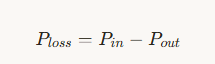
- Total losses Ploss: the difference between input and output
By definition:
and the efficiency η of a transformer is:
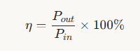
High‑efficiency transformers keep Ploss as low as practical over the intended operating range. Because losses show up as heat, they determine the required cooling, the operating temperature, and ultimately the expected lifetime of the insulation system. Even a small efficiency improvement can translate into large cost savings when the transformer operates continuously for 20 years or more.
3. Main Types of Transformer Losses
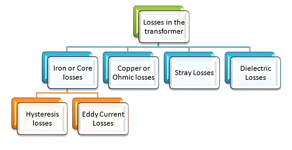
3.1 Core (Iron) Losses / No-Load Losses
Core losses, also known as iron losses or no‑load losses, arise from the alternating magnetic flux in the transformer core. They appear whenever you energise the transformer, even if you disconnect all loads from the secondary. Core loss depends mainly on the core material, frequency, maximum flux density, and core volume.
You usually break core losses into two main components:
First up, hysteresis loss. Basically, every time the AC flips, you have to magnetise the core, then demagnetise it, then magnetise it again the other way. All that flipping back and forth? Takes energy. How much depends on the steel you use—its hysteresis loop, how hard you push the flux, the frequency. Fancy stuff like grain-oriented silicon steel or amorphous metal? Way better than ordinary steel. Less energy wasted.
Then you’ve got eddy current loss. Picture this: that changing magnetic field inside the core? It actually stirs up little circulating currents—just swirling around inside the metal. And wherever current flows, you get heat. That’s eddy currents doing their thing. And here’s the kicker: double the frequency, or the flux density, or the thickness of the steel laminations? The losses don’t just double—they go up by the square. So they climb fast.
So how do you fight it? Manufacturers get clever. They use thin laminations—coated so they’re insulated from each other—made from high-resistivity steel or amorphous alloys. They dial in the flux density just right. And they design step-lap joints in the core to stop those nasty local hot spots where the core saturates and the magnetising current spikes.
3.2 Copper (Winding) Losses / Load Losses
Copper losses, also called winding losses or load losses, originate from the resistance of the transformer windings. When current flows through the windings, they dissipate power as heat according to the familiar relationship:
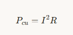
Copper loss increases with the square of the current. As the load increases, the current rises and copper losses grow rapidly. At or near full load, copper losses often dominate the total losses, especially in smaller or medium‑size transformers.
In addition to the simple I2R component, you also encounter extra losses due to skin effect and proximity effect:
- Skin effect concentrates current near the surface of the conductor at higher frequencies, effectively increasing its resistance.
- Proximity effect arises when alternating currents in nearby conductors interact magnetically and distort the current distribution, again increasing effective resistance and losses.
Engineers reduce copper losses by using high‑conductivity materials such as copper, increasing conductor cross‑section, optimising winding geometry, and minimising unnecessary lead length. For procurement teams, the specified load loss at rated current gives a clear indicator of how much energy the transformer will dissipate under typical loading.
3.3 Stray Losses in Structural Parts
Okay, stray losses. These are a bit sneakier.
Here’s what happens: not all the magnetic flux stays nicely inside the core where it belongs. Some of it leaks out—it doesn’t link both windings properly. And when that stray leakage flux hits conductive stuff nearby—like the tank, the core clamps, the frame, or any other metal bits hanging around—it induces currents in them. Those currents don’t help move power to the load. They just heat things up. Create local hot spots you didn’t plan for.
So where do these losses show up? Depends entirely on how you’ve laid the transformer out. The winding arrangement. The shape of the core. The geometry of the tank and yokes. Whether you’ve put in electromagnetic shields or not. All of that matters.
Designers fight back with magnetic shunts. Shields. Careful routing of leads and busbars. Basically, anything to corral that leakage flux and keep it from causing trouble.
Now, here’s the thing. Stray losses? Usually smaller than core losses or copper losses. So on paper, they don’t look like a big deal. But don’t ignore them. Because where they show up matters. They can drive local temperature rises. Create thermal stress right where you don’t want it. And if you lose control of stray flux? You get unexpected hot spots. And those spots? They age fast. Insulation breaks down quicker there. So a small loss in the wrong place can cause big problems down the line.
3.4 Dielectric Losses in Insulation
Dielectric losses happen in insulating materials. These materials include transformer oil, paper, pressboard, and solid insulation systems. The losses occur when these materials face alternating electric fields.
Imperfections in the dielectric material increase these losses. Moisture makes them worse. Contamination is another factor. Ageing of the insulation also adds to dielectric loss.
In many distribution transformers, dielectric losses stay small. Core and copper losses usually dwarf them. But in high-voltage transformers, they matter more. Extra-high-voltage transformers also see bigger dielectric losses.
Engineers use a specific measure for these losses. They call it the dissipation factor. Another name is loss tangent, or tan δ. Periodic tan δ testing helps monitor insulation health. The test can detect when insulation starts to deteriorate.
To reduce dielectric loss, start with quality materials. Use high-grade insulation from the beginning. Careful drying and processing during manufacturing help too. Keep moisture content low throughout the transformer’s life. Good oil filtration makes a difference. Regular oil maintenance also keeps dielectric loss under control.
3.5 No-Load vs Load Losses: A Side-by-Side Comparison
You can summarise the main differences between no‑load and load losses as follows:
- Dependence on load: No‑load loss remains almost constant regardless of load current; load loss increases roughly with the square of the load current.
- Main components: No‑load loss includes hysteresis and eddy current losses in the core; load loss includes I2R losses in windings and additional stray losses.
- When they occur: No‑load loss appears whenever the transformer stays energised, even at zero load; load loss appears only when the transformer carries current.
- Economic impact: No‑load losses dominate in lightly loaded, always‑on transformers such as many distribution transformers; load losses dominate in heavily loaded industrial or process transformers.
For both engineers and buyers, this split is crucial. You optimise core losses primarily through core design and material choice, while you manage load losses through winding design, conductor selection, and system loading strategy.
If you are planning a new project or replacing aging transformers, you can use this guide as a checklist—and reach out to our engineers for a tailored loss and efficiency assessment.
🚀 Get Your Free Loss Calculator
4. How Transformer Losses Affect Efficiency and Thermal Performance
4.1 Efficiency Curves and the Optimal Loading Point
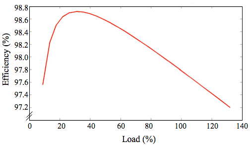
The total losses of a transformer combine two main parts: relatively constant core losses and variable load losses. As the load increases from zero, load losses start small and grow with current, whereas core losses stay roughly constant. Efficiency initially rises as the useful output power increases faster than total losses, then reaches a maximum, and eventually decreases as increasing copper losses dominate.
The loading point at which core loss equals copper loss often lies near the point of maximum efficiency for many transformer designs. In practice, engineers rarely operate exactly at this point, but this concept provides a useful guideline. For transformers that run at low average loading, reducing core loss gives more benefit; for transformers near full load for long periods, reducing load loss yields bigger savings.
You will find efficiency curves in transformer data sheets. Look closely at them. Check the claimed efficiency at different load levels. These levels are often shown as percentages. Common examples are 50%, 75%, and 100% of rated load. Pay attention to the power factor stated for these values.
These numbers serve a purpose. They help you make a better choice. You can match the transformer to your facility’s actual load profile. Your load may vary during the day. The right transformer should perform well at your typical operating points.
4.2 Overloading, Underloading, and Loss of Life
Loading conditions affect both losses and lifetime. When you overload a transformer for extended periods, the current increases, copper losses rise sharply, and internal temperatures climb. Elevated temperature accelerates thermal ageing of insulation and leads to faster loss of life. Standards provide guidelines for permissible short‑term overloads, but chronic overload will reduce expected lifetime significantly.
Underloading has the opposite effect on losses: copper losses remain low, but no‑load losses still run continuously. In lightly loaded distribution networks, this situation leads to sub‑optimal efficiency, because the system consumes core loss without delivering much useful power. Although underloading usually does not harm the transformer itself, it wastes energy and money.
You need to think about transformer sizing from a planning perspective. The goal is simple. You want the transformer to run in a healthy loading window. And you want it to stay there for most of its life.
Real-world conditions make this harder. Loads change throughout the day. Seasons bring different demands. Redundancy requirements add another layer. All these factors complicate the picture.
But there is a way to make better decisions. You need to understand how transformer losses behave at different loads. This knowledge helps you choose the right ratings. It also guides your loading policies. You can plan for the long term instead of just reacting.
International loading guides from IEC and IEEE explain how loading and temperature affect transformer loss of life.
4.3 Cooling Systems and Loss-Induced Heating
Transformer losses convert electrical energy into heat that the cooling system must remove. The magnitude and distribution of core, copper, stray, and dielectric losses determine temperature rise in the windings, core, and oil or air. Excessive temperature leads to accelerated insulation ageing and potential failure.
Transformers generate heat from losses. This heat needs to be managed. Manufacturers use different cooling methods.
Dry-type transformers often use natural air cooling. Air simply flows around the unit. It carries heat away.
Oil-immersed transformers work differently. Some use natural oil circulation. The hot oil rises naturally. Cooler oil takes its place. Other designs force the oil to circulate. Pumps keep the oil moving.
Radiators also help remove heat. Some use forced air to cool the oil. Fans blow air across the radiator surfaces. Others use water for cooling. Water carries the heat away more effectively.
These cooling choices tell you something. They reflect the expected losses. They also match the planned operating conditions. A transformer with higher losses needs more cooling. A tough operating environment demands a robust cooling design. High‑loss designs require larger tanks and more extensive cooling surfaces to keep temperatures within specified limits.
When you reduce transformer losses, you lower not only direct electrical losses but also the burden on cooling systems. In energy‑sensitive environments such as data centers, this translates into lower overall power usage effectiveness (PUE) and smaller HVAC systems.
5. From Watts to Dollars: Calculating the Cost of Transformer Losses
5.1 Estimating Annual Energy Cost of Losses
To turn transformer losses into economic numbers, you can follow a straightforward process. Suppose a manufacturer provides:
- No‑load loss at rated voltage: P0 (kW)
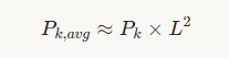
- Load loss at rated current and specified temperature: Pk(kW)
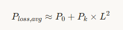
First, estimate the average loading LLas a fraction of rated power over the year. Load loss scales approximately with the square of loading, so average load loss becomes:
Total average loss power is then:
Multiply this by the annual operating hours hhand the energy price ccto estimate the yearly energy cost:
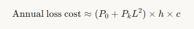
This simple calculation already reveals how sensitive the energy cost is to both no‑load loss and load loss. Utilities that run transformers 24 hours a day with low loading see a strong impact from P0, while industrial users with high loading see a stronger impact from Pk.
5.2 A Simple Lifecycle Cost (LCC / TCO) Framework
Purchase price alone does not tell you which transformer is cheaper over its full lifetime. A transformer with lower losses usually costs more upfront because it uses better materials and more copper or larger cores. However, when you add up 15–25 years of energy losses, the more efficient transformer often wins.
You can define a simple total cost of ownership (TCO) model for a transformer:TCO=Purchase price+Capitalised no‑load loss+Capitalised load loss+Maintenance costTCO=Purchase price+Capitalised no‑load loss+Capitalised load loss+Maintenance cost
Capitalised loss terms represent the present value of future energy costs associated with no‑load and load losses. To approximate them, you multiply the specified losses by representative operating hours and energy prices over the expected lifetime, then discount them to present value. Even without detailed financial modelling, you can compare two transformers by estimating annual loss costs and multiplying by the planned lifetime.
When you examine offers where one transformer has lower purchase price but higher losses, and another has higher price but lower losses, this TCO framework helps you compute a payback period. Many real‑world projects show payback periods of only a few years for upgrading to high‑efficiency transformers, especially where energy prices are high and utilisation is significant.
5.3 Why Procurement Should Ask for Loss Guarantees
For procurement teams, loss values should not just be “informative” data in a catalogue; they should become contractual guarantees. Manufacturers normally specify guaranteed no‑load loss and load loss at defined conditions, along with test tolerances. Tender documents can require that actual tested losses not exceed guaranteed values, and they can define penalties if they do.
When you require guaranteed losses, you create a clear basis for comparing bids not only on price but also on performance. You also ensure that the transformers you receive actually deliver the energy performance you used in your lifecycle cost calculations. Without such guarantees, you risk accepting units with higher‑than‑expected losses that erode your business case.
Want to quickly estimate how much transformer losses cost you every year? Try our free transformer loss and lifecycle cost calculator.
⚡ Talk to Our Transformer Experts Now
6. Design Strategies to Reduce Transformer Losses (For Engineers)
6.1 Core Material and Geometry Optimisation
Engineers can reduce core losses significantly through careful selection of core materials and geometry. Grain‑oriented silicon steel has long served as the standard material for power transformer cores because it exhibits low hysteresis and eddy current losses along the rolling direction. More recently, amorphous metal cores have gained popularity in distribution transformers due to even lower core losses, although they come with higher material costs and different mechanical properties.
Lamination thickness, stacking factor, and joint design also influence core losses. Thin laminations with high electrical resistivity decrease eddy currents, while step‑lap joints distribute flux more uniformly and avoid local saturation at mitered corners. Limiting maximum flux density within the core, even if it increases core size, can further reduce both core loss and no‑load current.
6.2 Winding Design and Conductor Selection
Winding design gives you another way to cut losses. Designers often pick copper for windings. Copper conducts electricity very well. It also has good mechanical strength. Its thermal performance is solid too.
Some applications use aluminium windings instead. Aluminium costs less upfront. But it has higher resistance. For the same conductor size, load losses go up.
You can lower winding resistance in a few ways. Make the conductor cross-section bigger. Shorten the conductor length. Optimise the winding geometry. All these help.
Large currents bring extra challenges. Skin effect pushes current to the conductor surface. Proximity effect creates uneven current distribution. Designers fight back with special techniques. Transposed conductors come into play. Foils are another option. Multi-strand windings also see regular use. These keep effective resistance under control. They cut both copper losses and stray losses.
Engineers cannot ignore mechanical factors either. Windings must survive faults. Short-circuits create huge electromagnetic forces. Windings must stay rigid. Deformation changes the leakage flux paths. That alters stray losses. A good design balances everything. Electrical requirements matter. Thermal needs matter. Mechanical strength matters too.
6.3 Minimising Stray and Dielectric Losses
Stray losses arise in structural components where leakage flux induces currents. You can minimise them by controlling leakage flux paths and shielding sensitive regions. Common techniques include adding magnetic shunts near the windings, using non‑magnetic or low‑loss materials in selected structural parts, and placing shields between windings and tank walls.
Dielectric losses depend on insulation quality and condition. Engineers specify low-loss insulation systems. They dry and impregnate materials carefully during manufacturing. Clean insulation matters during service. Dry insulation matters too. Oil must stay clean. Solid insulation must stay dry. Proper sealing helps. Good oil processing helps. Periodic testing catches problems early. These measures keep dielectric losses low. They also extend transformer life.
6.4 Digital Design, Simulation, and Testing
Modern transformer design relies on simulation tools. Finite element analysis is a common example. The software models magnetic flux distribution. Stray fields can be visualised. Hot spots and mechanical stresses also appear in the simulation.
Engineers iterate designs digitally. Regions with high loss density become visible. Geometry can be adjusted. Materials can be changed. Shielding can be modified. All this work happens before any prototype is built.
Once a design reaches manufacturing, type tests and routine tests verify that actual losses match design expectations. No‑load and short‑circuit loss measurements form part of routine test programs for each unit. Careful correlation between simulation and test results helps improve future designs and ensures consistent performance.
7. Specification and Purchasing Guide (For Buyers and Procurement Teams)
7.1 Key Technical Parameters in Data Sheets
Buyers review transformer data sheets. Power rating gets top billing. Primary and secondary voltage follow. Impedance is another key check. But energy performance matters. Long-term cost matters. Several other parameters deserve close attention.
- No‑load loss (core loss) at rated voltage
- Load loss at rated current and reference temperature
- Efficiency at one or more load points
- Temperature rise limits for windings and oil
- Cooling method (for example, ONAN, ONAF, dry‑type, forced‑air)
- Insulation class and expected service life
By comparing these parameters across different offers, procurement teams can identify high‑loss and low‑loss designs. Two transformers with the same kVA rating can differ substantially in losses, leading to very different ownership costs.
7.2 Writing Loss-Focused Tender Specifications
Tender specifications can strongly influence the efficiency of transformers you receive. To encourage energy‑efficient designs, you can explicitly define maximum allowable no‑load and load losses in the specification. Alternatively, you can specify minimum efficiency classes according to relevant standards.
In addition, tender documents can require:
- Guaranteed values for no‑load and load losses
- Test reports that document measured losses for each unit
- Penalty clauses if measured losses exceed guaranteed values beyond tolerance
- Requirements for efficiency at specified partial load points
By writing loss‑focused tender specifications, you give manufacturers clear targets and create a level playing field. You also signal that your organisation values transformer efficiency and lifecycle cost, not just purchase price.
7.3 Balancing Purchase Price and TCO in Real Projects
Procurement teams often face pressure to choose the lowest initial price. However, when you consider a 20‑year service life and rising energy prices, an apparently cheap transformer with high losses can become the most expensive option in the long run. A better approach balances purchase price with expected energy costs.
In practice, you can prepare a simple comparison for each major transformer purchase: list each bid, record its no‑load and load loss values, estimate annual energy cost for typical loading, and multiply by the planned lifetime. Then add the purchase price. This exercise often reveals that a slightly higher purchase price for a low‑loss transformer pays back within a few years and yields net savings over its life.
8. Application Examples: Utilities, Industry, and Data Centers
8.1 Utility and Distribution Transformers
Utilities operate large fleets of distribution transformers scattered across networks. Many of these transformers remain energised permanently and carry moderate or low average loading. For these units, no‑load loss represents a major portion of total energy loss.
Utilities can specify low core loss transformers. This choice reduces system losses. Overall efficiency improves. CO₂ emissions go down. Each transformer offers a small percentage improvement. Multiply this across thousands of units. The savings become substantial.
Distribution networks run loss-reduction programs. These programs target transformer efficiency. They often rank high in cost-effectiveness. They are smart energy-efficiency measures.
8.2 Industrial Plants and Manufacturing Facilities
Industrial transformers serve heavy machinery. They feed production lines. They power drives and large motors. Loading profiles vary widely. Some units run near rated load for long periods. Others see frequent starts and stops. Seasonal variations also occur.
Process reliability also matters. Excessive heating due to high copper and stray losses can reduce insulation life and lead to unexpected outages that disrupt production. Industrial users benefit from transformers with robust designs, low load losses, and appropriate overload capabilities, along with online monitoring to track temperature and loading.
8.3 Data Centers and Mission-Critical Loads
Data centers demand high availability. Mission-critical facilities have the same need. Energy usage must stay under strict control. Transformers in these facilities run around the clock. Loading is often moderate to high. No-load losses affect overall PUE. Load losses affect PUE too.
High-efficiency transformers help in two ways. Direct electrical losses go down. Waste heat also decreases. Less cooling power is needed. This saves even more energy. Operators invest in low-loss transformers. This supports a broader strategy. PUE improves. Operating costs drop. Sustainability targets become easier to meet.
Real-time monitoring plays a key role. Temperature gets tracked. Loading gets tracked. Condition gets tracked. This data helps maintain reliability. It also helps optimise operation.
9. Practical Checklists for Engineers and Buyers
9.1 Checklist for Design and Engineering Teams
Engineers can use the following checklist when designing or selecting transformers:
- Have you selected core materials and flux density to minimise core loss while meeting cost targets?
- Have you optimised winding design to keep I2RI2R and stray losses within acceptable limits?
- Does the cooling system handle worst‑case losses and ambient conditions without exceeding temperature rise limits?
- Have you evaluated efficiency at realistic loading points, not only at full load?
- Do you plan to monitor key parameters such as load, temperature, and oil condition during operation?
9.2 Checklist for Procurement and Tender Evaluation
Procurement teams can apply this checklist when preparing and evaluating tenders:
- Do tender documents specify maximum allowable no‑load and load losses or minimum efficiency classes?
- Do all bidders quote guaranteed values for losses under clearly defined conditions?
- Have you estimated lifecycle energy cost for each bid using realistic loading assumptions and energy prices?
- Do you consider penalty clauses or price adjustments if measured losses exceed guarantees?
- Does your evaluation process balance purchase price with total cost of ownership?
10. FAQs on Transformer Losses and Efficiency
Q1: What are the main types of transformer losses?
The main types include core (iron) losses, copper (winding) losses, stray losses in structural parts, and dielectric losses in insulation. Core losses are mostly independent of load, while copper losses increase with current.
Q2: Why do no‑load losses matter if my transformer is lightly loaded?
No‑load losses occur whenever the transformer is energised, even at zero load. In lightly loaded systems, they can dominate total energy losses over time and drive up operating costs.
Q3: How can I reduce transformer losses in an existing installation?
You can optimise loading across multiple transformers, avoid unnecessary energisation of lightly loaded units, improve cooling to reduce temperature‑dependent losses, and ensure proper maintenance of insulation and oil. In some cases, replacing old, high‑loss transformers with modern high‑efficiency units delivers strong economic returns.
Q4: Does higher efficiency always mean higher purchase price?
Higher efficiency usually requires better materials and more copper or larger cores, so purchase price often increases. However, the reduced energy losses over the lifetime typically offset the initial cost difference and yield net savings.
Q5: What should I ask manufacturers when requesting transformer quotations?
Request guaranteed no‑load and load loss values, efficiency at relevant load points, temperature rise data, and test reports. Ask for technical clarification on core materials, winding conductors, and cooling arrangements to understand how they affect losses and lifetime.
11. Key Takeaways and Next Steps
Transformer losses directly affect efficiency, operating cost, and reliability. Core losses dominate in lightly loaded, always‑on transformers, while copper losses dominate in heavily loaded units. You can reduce losses through better core and winding design, careful control of stray and dielectric losses, and by selecting high‑efficiency transformers during procurement.
For engineers, this means integrating loss optimisation into design, simulation, and specification. For buyers and procurement teams, it means evaluating offers based on total cost of ownership and demanding clear loss guarantees. When both groups work together, organisations can achieve lower energy bills, longer transformer life, and improved sustainability.
If you need help evaluating transformer offers, our team can review data sheets and loss figures with you.