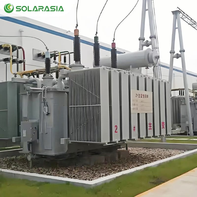
In modern power systems, transformers are not merely tools for voltage conversion; they are the core guarantee for grid stability and efficient energy utilization. Among them, Öltransformator are the preferred choice for power plants, transmission grids, industrial production, and renewable energy power stations due to their excellent cooling and insulation performance.
For corporate clients, selecting the right Oil Immersed Transformer is not only crucial for equipment safety and lifespan but also directly impacts energy consumption costs, operation and maintenance expenses, and return on investment (ROI). This article provides an in-depth analysis of the technical details and application value of oil-immersed transformers and shares our practical project experience.
I. What is an Oil-Immersed Transformer?
An Oil-Immersed Transformer is one of the most widely used electrical devices in power systems. Its primary function is to safely and efficiently convert electrical energy from one voltage level to another. Its uniqueness lies in the fact that the core and windings inside the equipment are completely immersed in specialized insulating oil. This oil not only conducts and dissipates heat but also provides insulation and protection.
1. Core Functions
- Voltage Transformation: Achieves efficient transmission of electrical energy between different voltages through electromagnetic induction, meeting the needs of hierarchical power transmission and distribution.
- Cooling & Heat Dissipation: During operation, windings and the core generate copper losses and iron losses. The insulating oil rapidly absorbs this heat and transfers it to radiators or the tank wall, maintaining the equipment temperature within a safe range.
- Insulation & Protection: Insulating oil has high dielectric strength, fills gaps in the windings, and prevents partial discharges, flashovers, and breakdowns, significantly enhancing electrical safety and operational stability.
2. Mechanism of Oil Action
- Cooling Characteristics: Oil has high specific heat capacity and good fluidity, making it suitable for natural or forced circulation cooling.
- Insulation Characteristics: Oil’s ability to suppress arcs and partial discharges is far superior to air, effectively reducing risks caused by internal electric field concentration.
- Protective Characteristics: Oil isolates the internal components from moisture and oxygen in the air, slowing down the aging of insulating paper and extending equipment life.
3. Common Types of Insulating Oil
- Mineral Oil:
- Advantages: Low cost, readily available, mature performance.
- Disadvantages: Lower flash point (flammable); poorer environmental friendliness.
- Application: Common in outdoor substations and large grid projects.
- Natural Ester Oil (Vegetable-Based):
- Advantages: High flash point (>300°C), highly biodegradable, environmentally friendly, non-toxic.
- Characteristics: Significantly reduces fire and pollution risks even when used indoors, underground, or in densely populated areas.
- Application: Rail transit, data centers, underground substations, and other locations with high safety requirements.
- Synthetic Ester Oil (For specific applications):
- High stability, good oxidation resistance, but higher cost.
- Often used in special scenarios like nuclear power plants and military grids.
4. Application Value
Oil-immersed transformers are widely used due to their high capacity, long lifespan, and excellent heat dissipation performance in:
- Power system backbone grids (Transmission and distribution substations)
- Large-scale industries (Metallurgy, chemical, manufacturing)
- Transportation energy (Rail transit, ports, airports)
- Renewable energy power stations (PV, wind power grid-connection transformers)
They are not only the core equipment for power transmission but also a key guarantee for reliable power supply, energy saving, and safe operation for customers.
II. Oil Immersed Transformer Internal Structure & Components
An oil-immersed transformer may seem like “a large tank + coils + core,” but each internal component has strict design requirements and functional divisions. Any deficiency in design or maintenance can affect the equipment’s lifespan and reliability. Details are provided component by component below.
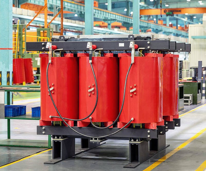
1. Core
- Material & Structure: Typically made from laminated Cold-Rolled Grain-Oriented (CRGO) silicon steel. Thinner laminations with better orientation and annealing processes result in lower hysteresis and eddy current losses. Laminations are stacked and insulated from each other with coatings or paper to reduce interlaminar eddy currents.
- Types: Common structures are “core-type” and “shell-type,” chosen based on application and capacity.
- Joint Processing: Joints use step-lap or staggered configurations to reduce flux concentration, noise, and eddy current losses.
- Mechanical Fixing: The core must be tightly clamped (with pressure plates, bolts) and include vibration damping pads to prevent loosening, increased noise, or metal fatigue caused by magnetostriction or short-circuit forces during long-term operation.
- Maintenance Risks: Core loosening increases low-frequency noise, causes local heating, and adds extra losses; moisture or oxidation reduces insulation and magnetic permeability.
2. Windings
- Conductor Material: Typically high-purity copper or aluminum. Copper offers better conductivity and mechanical strength; aluminum is lighter and lower cost. Conductor cross-sections can be rectangular, flat, or tubular (tubular aids oil flow).
- Winding Structure: Divided into High Voltage (HV) and Low Voltage (LV) windings. Disc windings or layer windings are often used in large capacity/high voltage transformers for improved voltage withstand and heat dissipation.
- Insulation System: Uses oil-impregnated paper (OIP), insulating boards, interlayer insulation (e.g., pressboard, Nomex, fiberglass), and processes like Vacuum Pressure Impregnation (VPI) or oil immersion to remove air, enhancing local insulation strength and heat transfer.
- Mechanical Reinforcement: Supports, clamps, and damping devices are installed at ends and crossings to withstand strong radial and axial electromagnetic forces during short circuits.
- Electrical Parameters: Winding design determines leakage reactance, short-circuit impedance, temperature rise distribution, and short-circuit forces, affecting voltage regulation and short-circuit withstand capability during operation.
- Maintenance Risks: Inter-turn shorts, winding deformation, insulating paper aging, and poor oil impregnation (trapped bubbles) are major fault sources, leading to partial discharge, hot spots, or even sparks.
3. Tank & Conservator
- Tank Material & Structure: Tanks are typically made of welded steel plates with anti-corrosion surface treatment; internal supports, fixing points, and oil channels are required. Tanks must be designed with sufficient mechanical strength to withstand oil pressure and forces from transport/short circuits.
- Conservator: Compensates for oil volume expansion/contraction with temperature changes, maintains relatively constant pressure inside the tank, and reduces direct oil-air contact, thus delaying oil oxidation and moisture absorption.
- Sealing & Secondary Containment: This is typically achieved using floating seals or gaskets. Furthermore, the design usually includes drain valves and oil collection channels specifically for maintenance and environmental protection. To enhance safety and compliance, modern designs additionally consider secondary containment (bunds) or oil collection pits in order to comply with stringent environmental regulations.
- Maintenance Points: Inspect tank welds, check for corrosion, perform regular visual and ultrasonic checks for oil leaks.
4. Breather / Dehydrating Breather
- Function: The conservator connects to the atmosphere via the breather; air enters and exits with temperature changes. The breather contains a desiccant (often color-indicating silica gel) to absorb moisture from the air, preventing it from entering the oil.
- Maintenance: Silica gel changes color as it absorbs moisture (e.g., blue → pink) and needs regular replacement or regeneration. Saturated silica gel accelerates moisture increase in the oil, reducing dielectric strength and promoting insulation aging.
- Alternative: Some high-end systems use sealed tanks filled with inert gas (like nitrogen) to completely isolate the oil from the atmosphere, further extending oil life.
5. Oil Level Gauge & Temperature Instruments
- Oil Level Gauge: Usually installed on the conservator or tank side for easy visual inspection; often equipped with alarm switches for remote monitoring.
- Temperature Measurement:
- Top Oil Temperature: Reflects overall tank temperature, measured by temperature sensors (RTD, thermocouple) connected to the control cabinet.
- Winding Hot-Spot Temperature: More directly reflects insulation aging risk, typically estimated via embedded RTDs or oil-temperature/current models.
- Temperature Control & Interlock: Fans or oil pumps can start automatically upon exceeding set temperatures, or alarm/trip logic can be triggered.
- Maintenance & Calibration: Temperature sensors require regular calibration; oil gauge seals and reading mechanisms must remain sensitive and leak-free.
6. Protection Devices
- Buchholz Relay / Gas Relay: Installed in the pipe between the conservator and the main tank. Detects slow gas accumulation (minor faults or local overheating) and rapid gas surges (severe arcing or explosion). Typically has two stages: alarm for minor gas and trip for major surge.
- Pressure Relief Valve: Automatically vents pressure during rapid internal pressure rise to avoid tank rupture or explosion.
- Tap-Changer: Adjusts output voltage (typical range ±10% to ±16%). Types include Off-Circuit Tap Changers (OCTC) and On-Load Tap Changers (OLTC). OLTC offers more flexibility but is structurally complex and requires more maintenance.
- Overtemperature, Overpressure, Overcurrent Relays: Provide graded protection and automatic tripping based on temperature and current measurements.
- Grounding & Terminals: Terminal outlets (bushings) must have good sealing and insulation; grounding terminals facilitate maintenance and fault current discharge.
- Maintenance Points: Buchholz relay sensitivity, pressure valve set point, tap-changer contact wear, and carbon dust accumulation in oil require regular inspection.
7. Other Key Components (Radiators, Bushings, Circuit Breakers, etc.)
- Radiators: External radiators increase heat exchange area to improve oil cooling efficiency, often interlocked with fans (Forced Air) or oil pumps (Forced Oil).
- Bushings: Specifically designed for this purpose, bushings are used to bring winding connections outside the tank. In terms of construction, materials include porcelain and composite, while internal insulation is often oil-impregnated paper or dry composite. To ensure long-term reliability, bushings require regular diagnostic tests like Power Factor/Capacitance, since capacitance unbalance or increased dielectric loss can indicate aging and potential failure.
- Oil Valves (Sampling/Drain): Facilitate online or offline sampling for DGA, moisture, acidity tests; also used for oil filtering, degassing, and regeneration.
III. Working Mechanism of Oil-Immersed Transformers
Explained from physical and electrical engineering perspectives, divided into the “Electromagnetic Energy Conversion Chain” and the “Heat-Oil Cooling Chain.”
1. Electromagnetic Energy Conversion
- Electromagnetic Induction: AC current in the primary winding creates an alternating magnetic flux around the coil, which then circulates through the low-reluctance path provided by the core. Subsequently, according to Faraday’s Law, the changing flux linking the secondary winding induces a voltage proportional to the number of turns (V ∝ N).
- No-Load & Load Behavior:
- No-Load: During no-load operation, the primary winding consequently only requires a small exciting current to magnetize the core. As a result, iron losses (hysteresis and eddy current) along with a minimal no-load current are the main losses.
- On-Load: Under load, the secondary output current inevitably causes additional voltage drops (I·R) and leakage reactance drops (jωLσ). To compensate for this, the winding must draw additional current from the primary side in order to maintain the magnetic flux and output voltage, ultimately resulting in load losses, known as copper losses.
- Internal Impedance & Short Circuit: The short-circuit impedance (usually expressed as percentage impedance) between windings and core determines the short-circuit current magnitude during faults and affects voltage drop and regulation during operation.
- Vector Group & Phase: For three-phase transformers, the winding connection (Y/D, D/Y, Y/Y, etc.) determines phase relationships, the need for neutral grounding, and parallel operation feasibility.
2. Heat-Oil Cooling Chain
- Heat Sources: Main heat sources are iron losses (concentrated in the core) and copper losses (from winding resistance). Partial discharges or poor contacts can also create hot spots.
- Oil’s Heat Transfer Role: Oil directly contacts windings and insulation, absorbing heat. Through natural convection or forced circulation (pumps), oil carries heat to radiators (or heat exchangers), where it is dissipated to air or water. Oil’s thermal conductivity and viscosity affect cooling efficiency.
- Hot Spots & Insulation Aging: Insulation material aging rate is closely related to temperature (insulation life decreases exponentially with temperature rise). Thus, controlling winding hot spots and good cooling design are core to extending transformer life.
- Oil Chemical Changes: High temperature, oxygen, and moisture cause mineral oil to oxidize, increasing acidity and forming soluble/insoluble acidic products and sludge. Gases generated in the oil (e.g., H₂, CH₄, C₂H₂, CO) are key evidence for DGA fault diagnosis.
3. Fault Detection Working Principles
- Dissolved Gas Analysis (DGA): Specifically, different gases indicate different faults: small H₂/CH₄ suggests partial discharge or thermal decomposition; meanwhile, C₂H₂ often indicates arcing; and rising CO/CO₂ suggests heating or decomposition of oil or solid insulation. Therefore, regular or online DGA allows early detection of potential faults.
- Buchholz Relay Logic: Slowly released gas is detected by the relay’s float, triggering an alarm. A rapid gas surge (e.g., from arcing) creates an oil flow surge that triggers an instantaneous trip, protecting the equipment and limiting catastrophic failure.
- Partial Discharge Detection: UHF electromagnetic waves or acoustic waves generated by discharges can be captured by sensors to locate and assess insulation defects.
Common Failure Modes & Early Signs
- Increased moisture & acidity in oil → Decreased dielectric strength, insulation softening → Signs: Increased dielectric loss/failed withstand voltage test, rising CO in DGA.
- Winding inter-turn short → Local heating, hot spot → Signs: Local temperature rise, rising light hydrocarbons in DGA or PD signals.
- Buchholz trip/Pressure relief activation → Sign: Internal arcing or severe heating occurred.
- Bushing cracking/leaking → Falling oil level, visible oil stains, abnormal grounding current.
- Tap-changer contact wear → Voltage fluctuations, increased contact resistance, abnormal noises.
IV. Oil Immersed Transformer Cooling Methods & Performance Differences
Losses in oil immersed transformers convert to heat. Ineffective heat dissipation leads to insulation aging, winding damage, or equipment failure. Thus, the choice of cooling method directly impacts equipment life, operational efficiency, and reliability.
1. Common Cooling Methods (IEEE Designations)
- ONAN (Oil Natural Air Natural):
- Mechanism: Relies on natural oil convection and natural air cooling.
- Characteristics: Simple structure, no extra cooling equipment, low operating noise.
- Application: Small to medium capacity (typically <10 MVA), e.g., distribution transformers, dedicated industrial transformers.
- ONAF (Oil Natural Air Forced):
- Mechanism: Natural oil circulation, fans added to radiators.
- Characteristics: Fans can be activated under high load, increasing cooling capacity by ~30–50%.
- Application: Medium capacity transformers (10–60 MVA), e.g., regional substations.
- OFAF (Oil Forced Air Forced):
- Mechanism: Oil pumps force oil circulation, fans force air cooling.
- Characteristics: High cooling efficiency, stable temperature rise control, suitable for long-term heavy load operation.
- Application: Large capacity power transformers (>60 MVA), especially in urban main grids and heavy industry.
- OFWF (Oil Forced Water Forced):
- Mechanism: Oil pumps force oil circulation, heat is transferred to cooling water via a heat exchanger.
- Characteristics: Excellent heat dissipation, not limited by ambient air temperature; but system is complex, requires clean and reliable water source.
- Application: Underground substations, tunnels, data centers where space is limited and low noise is required.
2. Performance Differences & Design Indicators
- Rated Capacity Range: Oil-immersed transformers range from hundreds of kVA to hundreds of MVA. Cooling method choice is closely related to capacity.
- Insulation Life: Under good maintenance, high-quality mineral oil transformers can last 30–40 years. Devices using natural ester oil offer longer lifespan, better safety, and environmental benefits.
- Energy Efficiency: New-generation energy-efficient transformers (e.g., S11, S13 series) significantly reduce no-load and load losses through optimized core materials, winding structures, and cooling design, improving operating efficiency by potentially 1-2% (Note: 10-20% overall efficiency gain seems high; adjusted to a more plausible figure related to loss reduction).
- Operational Stability: Equipment using OFAF or OFWF offers stronger overload capability and better temperature rise control, suitable for fluctuating power demand and long-term high-load conditions.
3. Customer Focus Points
- Cost-Benefit Balance: ONAN has the lowest cost, suitable for general distribution. OFWF has the highest cost but offers long-term energy savings and high reliability for critical loads.
- Installation Environment: Underground/indoor substations favor natural ester oil + water cooling systems for environmental and safety benefits.
- Operational Efficiency: Large energy users and grid companies focus on high-efficiency products like the S13 series to reduce operating costs and comply with green energy policies.
V. Performance Indicators & International Standards
Performance indicators and standards directly determine the reliability and value of oil-immersed transformers during design, manufacturing, and procurement. The following aspects are crucial for customer selection:
- Rated Capacity: Capacity typically ranges from 100 kVA small distribution transformers up to several hundred MVA extra-large power transformers, thereby catering to diverse needs from factories and commercial parks all the way to national grid projects. Consequently, larger capacities demand significantly higher requirements for cooling systems, winding structures, and insulation class.
- Voltage Class: Common ranges cover medium/low voltages like 6 kV, 10 kV, 35 kV, up to extra-high voltages like 220 kV, 500 kV, even 750 kV. This means oil-immersed transformers are used for both industrial park distribution and cross-regional high-voltage transmission projects.
- Energy Efficiency Class: Complies with international standards like IEC 60076, IEEE C57, GB/T 6451. Products can meet EU EcoDesign Tier 2, Chinese GB energy standards, or US DOE efficiency standards based on project requirements. High-efficiency products significantly reduce electrical losses over their lifecycle, saving users substantial energy costs.
- Losses Control:
- No-load Loss: Primarily consists of core hysteresis and eddy current losses, controlled using high-quality silicon steel and optimized stacking processes.
- Load Loss: Caused by winding resistance (I²R) and stray losses, reduced by using low-resistance copper conductors and optimized coil design.
- International standards require manufacturers to perform type tests before factory shipment to ensure loss data is accurate and reliable.
- Insulation Class:
- Class A (105°C): Suitable for general conditions.
- Class F (155°C): Suitable for high-temperature, long-duration operation, e.g., tropical regions or high-load industrial sites.
- Different insulation classes directly relate to transformer lifespan and maintenance intervals.
VI. Oil Immersed Transformer Safety & Maintenance
As core equipment for grids and industrial facilities, the safety and reliability of oil-immersed transformers are key to their long-term stable operation.
1. Fire & Environmental Protection
- Mineral Oil Type: Requires fire walls, oil containment pits, and fire suppression systems. Suitable for above-ground substations or areas with lower environmental requirements.
- Natural Ester Oil Type: High flash point (>300°C), biodegradable. Suitable for underground substations, data centers, hospitals, tunnels, and other places with high fire safety and environmental requirements. Using natural ester oil can also reduce fire spread risk, improve insurance ratings, and offer advantages in project approvals.
2. Regular Testing & Predictive Maintenance
- Dissolved Gas Analysis (DGA): Detects concentrations of gases like Hydrogen, Acetylene, Carbon Monoxide to identify partial discharge, overheating, or insulation aging issues early.
- Oil Quality Testing: Checks acidity, moisture content, dielectric strength, breakdown voltage to ensure the insulating oil maintains excellent insulation and cooling properties.
- Infrared Thermography & Partial Discharge Testing: Detects winding hot spots and potential electrical faults without shutdown, preventing unexpected outages.
3. O&M Cost Advantages
- Regular Oil Replacement/Purification: Delays insulation aging, extending equipment life to 30–40 years.
- Smart Monitoring Systems: Integrated with SCADA or IoT platforms enable remote real-time monitoring of oil temperature, oil level, and load conditions, reducing manual inspection costs.
- Long-Term ROI: High-quality oil-immersed transformers offer the lowest total Life Cycle Cost (LCC), providing customers with low failure rates + high reliability + energy efficiency savings.
VII. Typical Application Scenarios
Due to their excellent insulation, cooling capability, and long life, oil-immersed transformers are widely used in various energy and industrial sectors:
- Power Plants: Act as step-up transformers, boosting generator output voltage (e.g., 6–35 kV) to transmission levels (e.g., 220–500 kV) to reduce energy loss over long distances. Their stability in high-voltage, high-power scenarios makes them core grid-connection equipment.
- Urban Distribution Grids: Used in distribution to step down high voltage (e.g., 35 kV, 110 kV) to utilization levels (e.g., 380/220 V) for residential, commercial complexes, hospitals, and schools. Their quiet operation and compact design suit dense urban environments.
- Heavy Industry: For sectors like smelting, electrolysis, mining, and heavy machinery manufacturing, oil-immersed transformers provide high-current, stable continuous power, avoiding huge economic losses from production interruptions.
- Renewable Energy Plants: Specifically, in PV plants and wind farms, oil-immersed transformers act as step-up units, converting and elevating low-voltage DC/AC to grid voltage, thereby ensuring efficient integration of renewable energy into the grid.
- Rail Transportation (Railway & Metro Systems): Furthermore, high-speed rail, subways, and light rail require high-capacity, reliable power systems. In this context, oil-immersed transformers provide stable power for traction substations, thereby ensuring high-speed operation and safety.
VIII. Industry Trends & Customer Opportunities
With the global energy transition and smart grid development, the oil-immersed transformer industry is undergoing significant changes:
- Green Transition: Consequently, traditional mineral oil, being flammable and non-biodegradable, is gradually being replaced by natural and synthetic ester oils. Moreover, these eco-friendly oils have high flash points (>300°C) and are biodegradable, reducing fire risks and meeting strict environmental regulations in markets like Europe and North America.
- Smart Monitoring: Using IoT + AI technology, transformers enable remote real-time monitoring of oil temperature, level, load, current, and dissolved gases. Predictive Maintenance identifies potential issues early, significantly reducing failure rates and outage losses.
- Energy Efficiency:
- Using amorphous alloy cores reduces iron losses by over 70% compared to traditional silicon steel.
- Low-loss windings and optimized cooling design further improve overall efficiency.
- Energy-efficient products (e.g., S13, SH15 series) save significant electricity costs over their lifecycle and comply with standards like EU EcoDesign Tier 2.
- Customized Solutions: Different industries have varying requirements, e.g.:
- Metro systems need low-noise design.
- Offshore wind farms require high corrosion resistance.
- Data centers need natural ester oil fire-safe solutions.
- Professional manufacturers can provide customized products based on the customer’s operating environment, voltage level, cooling method, and protection level.
IX. Why Choose Us?
In the Oil Immersed Transformer market, the supplier’s technical and service capabilities determine the long-term stable value for the customer.
- 15 Years of Industry Experience: In addition, we have deep expertise in the power and renewable energy sectors, serving 2000+ global clients with projects spanning European wind farms, North American industrial parks, and Asian rail transit, thereby accumulating rich cross-industry experience.
- Comprehensive International Certifications: Moreover, our products are designed and manufactured strictly according to IEC, IEEE, GB/T, ANSI, and Eco Design standards, and further validated through third-party testing and certification, thereby enabling seamless entry into major markets such as Europe, North America, the Middle East, and Asia.
- Customization Design Capability: Based on diverse client needs, we provide:
- Multiple voltage levels (6–750 kV)
- Various cooling methods (ONAN, ONAF, OFAF, OFWF)
- Special protection (anti-corrosion, fire resistance, low noise)
- Ensuring stable operation even in complex conditions.
- Full-Service Support (One-stop Service): From needs analysis, solution design, manufacturing, type testing, delivery, installation, to long-term operational support, we offer a closed-loop service system to maximize customer investment value.
- Proven Track Record:
- European Wind Farm: Natural ester oil step-up transformers meeting environmental and fire safety standards.
- North American Manufacturing: Supplied large capacity power transformers ensuring 24/7 continuous factory production.
- Asian Rail Transit: Provided highly reliable power supply solutions for metro traction systems.
In fact, an oil-immersed transformer is not just an electrical device; it is the core guarantee for power system stability and enhanced energy efficiency.
Therefore, if you are looking for highly reliable, internationally compliant, and customizable oil-immersed transformer solutions, simply contact us for professional technical support and a customized quote.
1 Comment