In modern electrical power systems, transformers play a critical role in ensuring efficient electricity transmission and distribution. Devices such as the oil immersed transformer are widely used in substations, industrial facilities, and power networks to handle high-capacity electrical loads. Understanding the transformer working principle is essential for engineers, technicians, and energy professionals who design and maintain reliable power systems.
The transformer working principle is based on the concept of electromagnetic induction, which allows electrical energy to transfer between circuits through a changing magnetic field. By adjusting voltage levels efficiently, transformers make long-distance power transmission possible while maintaining safe voltage levels for residential, commercial, and industrial applications.
Table of Contents
- Introduction to Transformers
- Transformer Working Principle
- Principle of Electromagnetic Induction
- Main Components of a Transformer
- Step-by-Step Transformer Operation Process
- Step-Up vs Step-Down Transformers
- Transformer Efficiency and Losses
- Factors Affecting Transformer Performance
- Applications of Transformers in Power Systems
- Industrial and Renewable Energy Transformer Use
- Transformer Selection Considerations
- Frequently Asked Questions
- Conclusion
1.Introduction to Transformers
Modern electrical infrastructure relies heavily on the Transformer, a device that transfers electrical energy between circuits through magnetic coupling. An electrical transformer is a static device that transfers electrical energy between circuits through electromagnetic induction. Engineers use transformers to change voltage levels, improve transmission efficiency, and ensure safe power distribution across residential, commercial, and industrial systems.
The transformer working principle is based on Electromagnetic Induction, which allows energy transfer through a changing magnetic field. When alternating current flows through one coil of wire, it generates a varying magnetic flux in the core. This magnetic flux induces voltage in another coil, allowing electrical energy to move from the primary circuit to the secondary circuit without direct electrical contact.
This simple yet powerful principle makes transformers essential components in power plants, transmission networks, substations, renewable energy systems, and industrial facilities. Without transformers, long-distance electricity transmission would be inefficient and costly because power losses increase dramatically when voltage remains low.
Understanding the transformer working principle helps engineers, technicians, and system designers optimize power systems, improve electrical safety, and select the appropriate transformer type for different applications.
In this guide, we will explain how transformers operate, examine their internal structure, and analyze how they convert voltage efficiently in modern power systems.
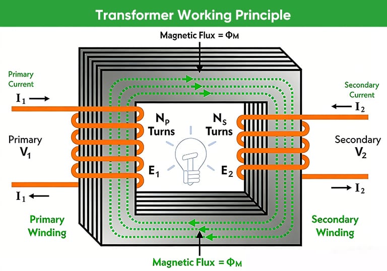
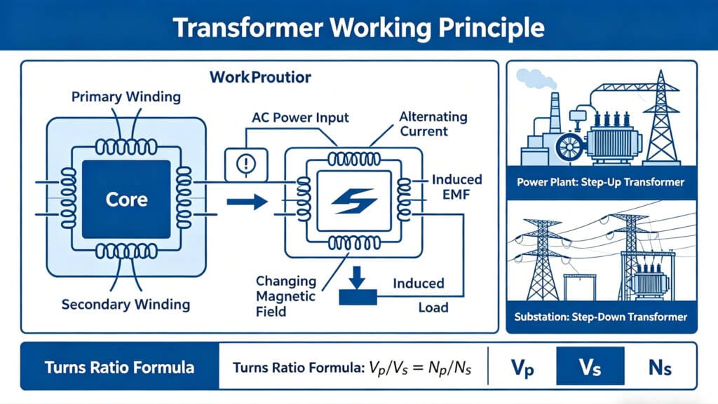
2.Transformer Working Principle
The transformer working principle relies on the interaction between magnetic fields and electrical conductors. When alternating current enters the primary winding of a transformer, it produces a constantly changing magnetic field around the coil. This magnetic field travels through the magnetic core and links with the secondary winding.
Because the magnetic field continuously changes direction and strength, it induces an electromotive force (EMF) in the secondary winding. This process converts electrical energy from one voltage level to another while maintaining the same frequency.
Engineers design transformers to either increase or decrease voltage depending on system requirements.
For example:
- Power plants use step-up transformers to increase voltage for long-distance transmission.
- Distribution substations use step-down transformers to reduce voltage for local consumption.
The fundamental relationship between voltage and the number of turns in each winding follows the transformer turns ratio equation:
V1/V2=N1/N2
Where:
| Symbol | Meaning |
|---|---|
| V1 | Primary Voltage |
| V2 | Secondary Voltage |
| N1 | Number of Primary Winding Turns |
| N2 | Number of Secondary Winding Turns |
This equation shows that voltage transformation depends directly on the ratio between the number of turns in each winding.
If the secondary winding has more turns than the primary winding, the transformer increases voltage. If it has fewer turns, the transformer reduces voltage.
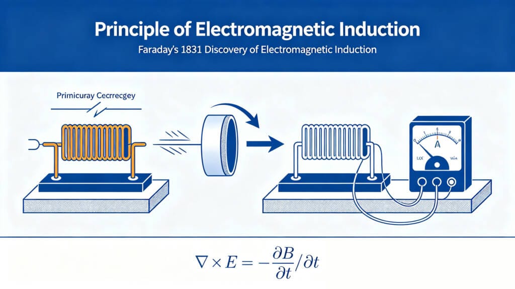
3.Principle of Electromagnetic Induction
The transformer working principle originates from electromagnetic induction, a concept discovered by Michael Faraday in 1831. Faraday demonstrated that a changing magnetic field can induce an electric current in a nearby conductor.
Transformers apply this concept using coils wrapped around a magnetic core. The alternating current flowing through the primary coil creates a magnetic flux that constantly expands and collapses.
This changing magnetic flux passes through the transformer core and links with the secondary winding. As the magnetic flux changes, it induces voltage in the secondary coil according to Faraday’s Law:
E=−N dΦ/dt
Where:
| Symbol | Description |
|---|---|
| E | Induced Voltage |
| N | Number of Coil Turns |
| Φ | Magnetic Flux |
| dΦ/dt | Rate of Change of Magnetic Flux |
Several key conditions must exist for electromagnetic induction to occur inside a transformer:
- The input current must be alternating (AC).
- The magnetic field must continuously change.
- The coils must share a magnetic path through the core.
These conditions explain why transformers cannot operate effectively with direct current. Direct current produces a constant magnetic field, which prevents voltage induction in the secondary winding.
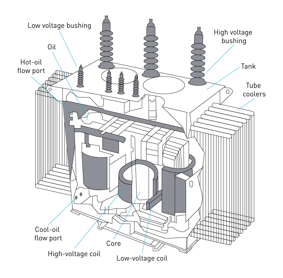
4.Main Components of a Transformer
A transformer contains several critical components that enable efficient electromagnetic energy transfer. Each part plays a specific role in maintaining electrical performance, insulation, and thermal stability.
Transformer Structure Overview
| Component | Function |
|---|---|
| Magnetic Core | Provides a low-resistance path for magnetic flux |
| Primary Winding | Receives electrical energy from the power source |
| Secondary Winding | Delivers transformed voltage to the load |
| Insulation System | Prevents electrical faults between windings |
| Cooling System | Dissipates heat generated during operation |
| Transformer Tank | Protects internal components and contains insulating oil |
Magnetic Core
The magnetic core forms the central path for magnetic flux inside the transformer. Manufacturers typically construct cores from laminated silicon steel sheets to reduce eddy current losses.
These laminations minimize energy loss while maintaining high magnetic permeability. A high-quality core improves transformer efficiency and reduces operating temperature.
Primary Winding
The primary winding connects directly to the input power supply. When alternating current flows through this winding, it generates the magnetic flux that drives the transformer working process.
Engineers design the primary winding to withstand system voltage, thermal stress, and electromagnetic forces.
Secondary Winding
The secondary winding receives energy from the magnetic field generated in the core. The voltage induced in this coil depends on the turns ratio between the primary and secondary windings.
This winding delivers electrical energy to the connected load, such as industrial equipment, residential circuits, or power distribution networks.
Insulation System
Transformers require strong insulation systems to prevent electrical faults between windings and the transformer core. Insulation materials include specialized papers, varnishes, and high-temperature polymers.
High-capacity transformers often use insulating oil to enhance both electrical insulation and cooling performance.
Cooling System
Transformers generate heat during operation due to copper losses and core losses. If the heat accumulates, it can damage insulation and reduce transformer lifespan.
Cooling systems maintain safe operating temperatures. Common cooling methods include:
| Cooling Method | Description |
|---|---|
| Oil Natural Air Natural (ONAN) | Natural oil and air circulation |
| Oil Natural Air Forced (ONAF) | Fans improve cooling performance |
| Oil Forced Air Forced (OFAF) | Pumps and fans increase heat dissipation |
Cooling design plays a major role in determining transformer capacity and reliability.
5.Step-by-Step Transformer Operation Process
Understanding the transformer working principle becomes easier when we analyze the complete operational sequence inside the device.
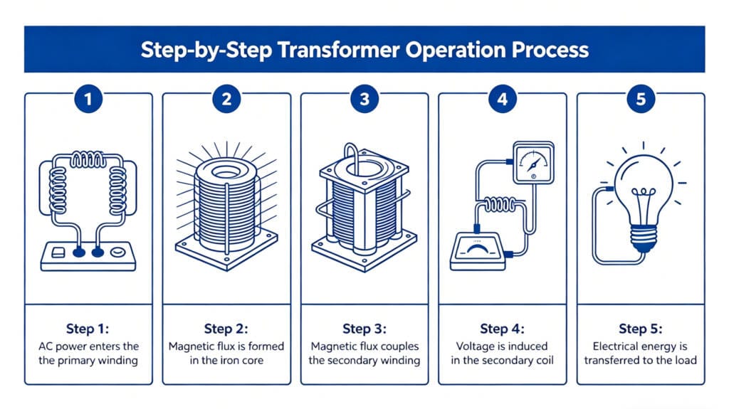
Step 1: AC Power Enters the Primary Winding
The process begins when alternating current flows through the primary winding. This current creates an alternating magnetic field around the coil.
Step 2: Magnetic Flux Forms in the Core
The magnetic field produced by the primary winding travels through the laminated steel core. The core concentrates the magnetic flux and directs it efficiently toward the secondary winding.
Step 3: Magnetic Flux Links the Secondary Winding
As the magnetic flux passes through the secondary coil, it continuously changes magnitude and direction. This changing flux interacts with the secondary winding conductors.
Step 4: Voltage Is Induced in the Secondary Coil
The varying magnetic field induces an electromotive force in the secondary winding. The magnitude of this voltage depends on the winding turns ratio.
Step 5: Electrical Energy Transfers to the Load
Once voltage appears across the secondary winding, electrical current flows into the connected load. This completes the transformer energy transfer process.
The entire process occurs without direct electrical contact between the input and output circuits, which improves safety and reliability.
6.Step-Up vs Step-Down Transformers
Engineers classify transformers based on their voltage transformation function. The two most common types are step-up transformers and step-down transformers. Both devices operate according to the same Transformer working principle, but their winding configurations produce different voltage outputs.
A step-up transformer increases voltage from the primary side to the secondary side. Engineers achieve this by designing the secondary winding with more turns than the primary winding. Increasing the number of turns increases the induced voltage according to the transformer turns ratio. Large oil immersed power transformers are commonly used in power plants to step up voltage before electricity enters the transmission grid.
Power generation facilities widely use step-up transformers because electricity must travel long distances through transmission networks. Higher transmission voltage reduces current and significantly decreases power loss during transmission.
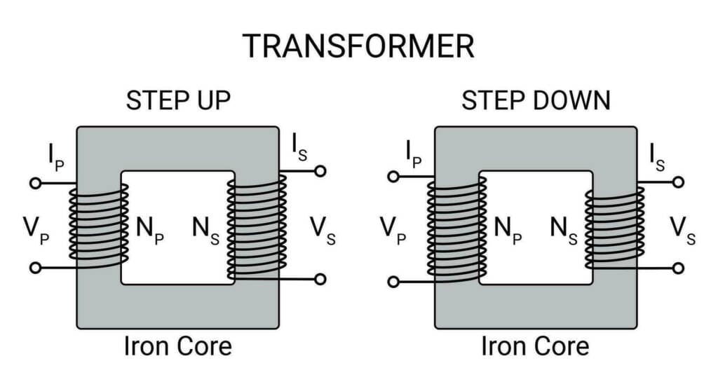
In contrast, a step-down transformer reduces voltage to a lower level suitable for residential, commercial, or industrial use. Engineers design these transformers with fewer turns in the secondary winding than in the primary winding.
Electric utilities install step-down transformers in substations and distribution networks to convert high transmission voltage into safe operating voltage for end users.
The table below summarizes the main differences between these two transformer types.
| Transformer Type | Voltage Relationship | Typical Application |
|---|---|---|
| Step-Up Transformer | Secondary voltage higher than primary voltage | Power plants, transmission systems |
| Step-Down Transformer | Secondary voltage lower than primary voltage | Distribution networks, industrial power systems |
Although their voltage outputs differ, both transformer types rely on the same Electromagnetic Induction mechanism to transfer energy between circuits.
Transformer Losses Calculation Example
To better understand how losses affect transformer performance, let’s look at a practical calculation example for a typical 100 kVA distribution transformer.
Given data:
- Rated capacity: 100 kVA
- Full-load copper loss (P_cu): 1.2 kW (at rated current)
- Iron loss / Core loss (P_iron): 0.35 kW (constant, no-load loss)
- Power factor (cosφ): 0.85
- Output power at full load: 100 kVA × 0.85 = 85 kW
Step-by-step calculation:
- Total losses at full load = Copper loss + Iron loss = 1.2 kW + 0.35 kW = 1.55 kW
- Input power = Output power + Total losses = 85 kW + 1.55 kW = 86.55 kW
- Efficiency (η) = (Output power / Input power) × 100% = (85 / 86.55) × 100% ≈ 98.21%
At 50% load (half load):
- Copper loss becomes (0.5)² × 1.2 kW = 0.3 kW (because copper loss ∝ I²)
- Iron loss remains 0.35 kW
- Total losses = 0.3 + 0.35 = 0.65 kW
- Output power = 42.5 kW
- Efficiency = (42.5 / (42.5 + 0.65)) × 100% ≈ 98.49% (often higher at partial load)
Loss Comparison Table:
| Load Condition | Copper Loss (kW) | Iron Loss (kW) | Total Loss (kW) | Efficiency (%) | Notes |
|---|---|---|---|---|---|
| No Load | 0 | 0.35 | 0.35 | – | Only core losses |
| 50% Load | 0.30 | 0.35 | 0.65 | 98.49 | Highest efficiency point often here |
| Full Load (100%) | 1.20 | 0.35 | 1.55 | 98.21 | Copper losses dominate |
| 75% Load | 0.675 | 0.35 | 1.025 | ~98.4 | Typical operating condition |
7.Transformer Efficiency and Losses
Transformers are among the most efficient electrical machines ever developed. Large power transformers often achieve efficiencies above 98–99%, which makes them essential for modern power systems.
However, no transformer can operate without energy loss. During operation, several physical processes convert a small portion of electrical energy into heat. Engineers classify these losses into two main categories: core losses and copper losses.
Core Losses
Core losses occur inside the transformer’s magnetic core. These losses exist even when the transformer operates without load because the magnetic field constantly changes inside the core.
Core losses consist of two main components:
Hysteresis Loss
Hysteresis loss results from the repeated magnetization and demagnetization of the core material. As magnetic domains continuously realign with the alternating magnetic field, they consume energy and generate heat.
Manufacturers reduce hysteresis loss by using high-grade silicon steel with excellent magnetic properties.
Eddy Current Loss
Eddy currents form when the alternating magnetic field induces circulating currents inside the conductive core material. These currents produce heat and waste energy.
To minimize eddy current losses, engineers construct transformer cores using thin laminated steel sheets separated by insulating layers.
Copper Losses
Copper losses occur in the transformer windings due to electrical resistance. As current flows through the winding conductors, the resistance converts electrical energy into heat.
Copper losses increase with load current and follow the relationship:
P=I2RP
Where:
| Parameter | Meaning |
|---|---|
| P | Power loss |
| I | Current |
| R | Winding resistance |
Engineers reduce copper losses by using high-purity copper conductors and optimizing winding design.
Transformer Loss Summary
| Loss Type | Cause | Occurs When |
|---|---|---|
| Hysteresis Loss | Magnetic domain realignment | Always |
| Eddy Current Loss | Circulating currents in core | Always |
| Copper Loss | Electrical resistance in windings | Under load |
Understanding these losses helps engineers improve transformer efficiency and thermal performance.
8.Factors Affecting Transformer Performance
Several engineering factors influence transformer performance, efficiency, and reliability. Designers must carefully balance these parameters when developing modern power transformers.
Core Material Quality
The magnetic core directly affects transformer efficiency. High-permeability materials allow magnetic flux to travel easily through the core, reducing energy loss.
Modern transformers often use grain-oriented silicon steel to improve magnetic performance and reduce hysteresis loss.
Winding Design
The configuration and insulation of transformer windings significantly influence electrical performance. Engineers must consider conductor size, insulation thickness, and winding arrangement.
A well-designed winding system reduces electrical resistance, improves cooling, and enhances operational reliability.
Cooling System Design
Transformers generate heat continuously during operation. If the temperature rises excessively, insulation materials degrade and equipment lifespan decreases.
Cooling systems maintain safe operating temperatures and improve long-term reliability.
Common cooling methods include:
| Cooling Type | Description |
|---|---|
| ONAN | Oil Natural Air Natural cooling |
| ONAF | Oil Natural Air Forced cooling |
| OFAF | Oil Forced Air Forced cooling |
Larger transformers require more advanced cooling systems to maintain stable operation under heavy load conditions.
Insulation System
The insulation system protects the transformer from electrical breakdown and internal faults. High-quality insulation materials ensure long-term performance under high voltage stress.
Insulation failures represent one of the most common causes of transformer malfunction. Therefore, manufacturers conduct extensive insulation testing during production.
9.Applications of Transformers in Power Systems
Transformers play a critical role in every stage of electrical power systems, from generation to final consumption. Their ability to efficiently change voltage levels makes them indispensable for modern energy infrastructure. Transformers play a critical role in modern power transmission systems by increasing voltage for long-distance electricity transfer.
Power Generation
Power plants generate electricity at relatively low voltage levels. Engineers use step-up transformers to increase the voltage before transmitting power over long distances.
Higher transmission voltage significantly reduces current flow, which minimizes transmission losses.
Power Transmission
High-voltage transmission networks transport electricity across hundreds or even thousands of kilometers. Transformers help maintain efficient energy transfer throughout the network.
Without transformers, electrical utilities would experience enormous power losses during transmission.
Power Distribution
When electricity reaches local distribution networks, utilities use step-down transformers to reduce voltage levels for residential and commercial consumption.
Distribution transformers deliver safe voltage levels suitable for household appliances and industrial equipment.
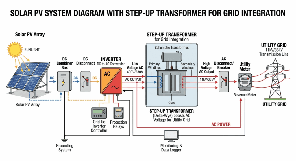
Solar PV Systems
In solar photovoltaic (PV) power plants, transformers play a critical role in integrating inverter output with the electrical grid. Solar panels generate DC electricity, which is converted to AC by inverters. However, the inverter output voltage (typically 400–1000 V AC) is usually too low for efficient long-distance transmission or direct grid connection.
Here, step-up transformers (also called inverter transformers or solar transformers) are used to boost the voltage to medium voltage levels (11 kV, 22 kV, or 33 kV). This voltage step-up significantly reduces current, thereby minimizing I²R transmission losses according to the transformer working principle.
Key functions of transformers in solar PV systems:
- Match inverter output to grid voltage requirements
- Provide galvanic isolation for safety and fault protection
- Handle harmonic distortions and power quality issues generated by inverters
- Enable efficient collection of power from multiple inverters in large-scale solar farms
For utility-scale solar projects, a typical setup includes:
- Inverter → Solar step-up transformer → Medium voltage collector system → Grid connection
At Solar Asia PV, we specialize in designing and supplying high-efficiency solar transformers that are optimized for PV applications, ensuring maximum energy yield and long-term reliability in harsh outdoor environments.
10.Industrial and Renewable Energy Transformer Use
In addition to traditional power systems, transformers play a vital role in industrial and renewable energy applications.
Industrial Power Systems
Industrial facilities require reliable and stable electrical power to operate heavy machinery and automation systems. Transformers provide voltage conversion and electrical isolation for manufacturing equipment.
Industries that rely heavily on transformers include:
- Steel manufacturing
- Mining operations
- Petrochemical plants
- Large manufacturing facilities
These industries require high-capacity transformers capable of operating continuously under heavy electrical loads.
Renewable Energy Systems
Renewable energy technologies such as solar and wind power also rely on transformers for efficient energy integration.
Solar power plants generate electricity through photovoltaic inverters. Transformers adjust the inverter output voltage to match grid requirements before connecting the system to the power network.
Wind turbines use step-up transformers to increase generated voltage before transmitting power to substations.
As renewable energy capacity continues to grow worldwide, transformer technology remains essential for integrating clean energy into modern electrical grids.
11.Transformer Selection Considerations
Selecting the correct transformer requires careful analysis of several technical factors. Engineers must evaluate system requirements, operating conditions, and long-term reliability.
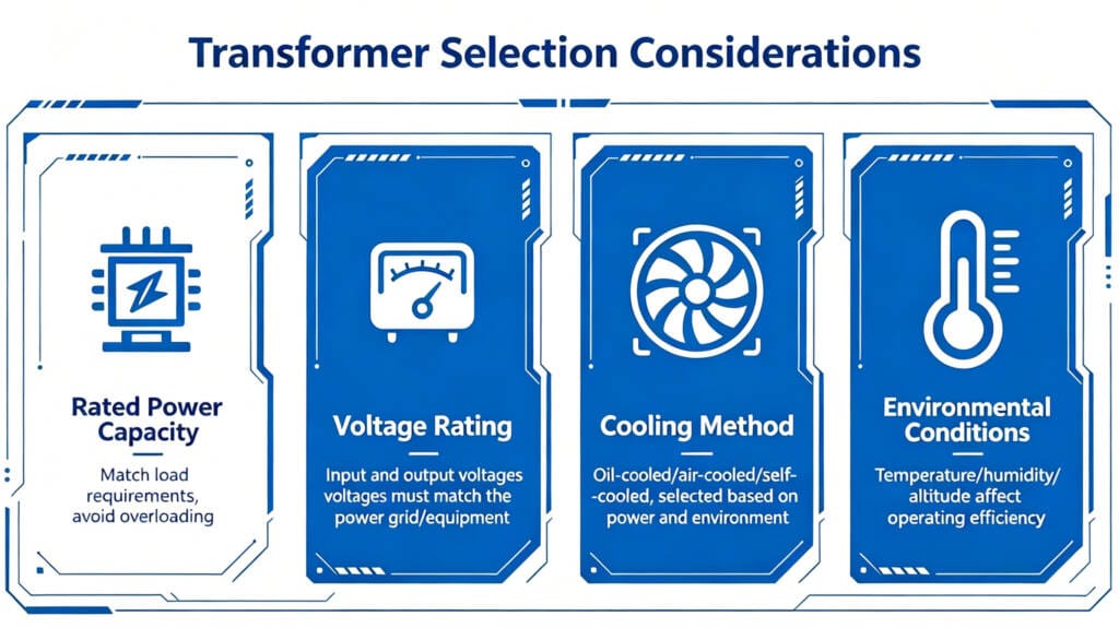
Key selection factors include:
Rated Power Capacity
Transformer capacity determines how much electrical power the device can safely handle. Engineers must choose a transformer rating that matches the expected load demand.
Voltage Ratings
Both primary and secondary voltage ratings must align with system voltage levels to ensure safe operation.
Cooling Method
Cooling design affects transformer performance, efficiency, and service life. Larger transformers require more advanced cooling systems.
Environmental Conditions
Environmental factors such as temperature, humidity, dust, and altitude can affect transformer performance. Engineers must select transformers that meet site-specific environmental conditions.
The following table summarizes common transformer selection parameters.
| Parameter | Description |
|---|---|
| Rated Capacity | Maximum power output |
| Voltage Rating | Primary and secondary voltage levels |
| Cooling Method | Heat dissipation system |
| Insulation Level | Ability to withstand electrical stress |
Proper transformer selection ensures efficient operation and long equipment lifespan.
12.Frequently Asked Questions
What is the working principle of a transformer?
The transformer working principle relies on electromagnetic induction. Alternating current flowing through the primary winding generates a changing magnetic field in the core. This magnetic field induces voltage in the secondary winding, transferring electrical energy between circuits.
Why do transformers only work with AC?
Transformers require a changing magnetic field to induce voltage in the secondary winding. Alternating current continuously changes direction and magnitude, which produces the required magnetic flux variation. Direct current does not create this changing magnetic field.
How do transformers change voltage?
Transformers change voltage by altering the ratio between the number of turns in the primary and secondary windings. A higher secondary winding turns count increases voltage, while fewer turns decrease voltage.
What determines transformer efficiency?
Transformer efficiency depends on several factors, including core material quality, winding resistance, cooling design, and operating load conditions.
How does a transformer work without moving parts?
Transformers operate purely on electromagnetic induction (Faraday’s Law). Alternating current in the primary winding creates a changing magnetic field in the core, which induces voltage in the secondary winding. No mechanical movement is required, making transformers highly reliable and low-maintenance static devices.
What is the difference between ideal and real transformer working principle?
An ideal transformer assumes 100% efficiency with no losses, no leakage flux, and zero winding resistance. In reality, practical transformers have core losses (hysteresis + eddy current), copper losses, and leakage flux, resulting in efficiency typically between 95–99%.
Why is the transformer efficiency highest at partial load rather than full load?
Iron losses are constant, while copper losses increase with the square of the load current. At around 50-75% load, the balance between these losses often results in peak efficiency.
How do transformers help reduce power losses in long-distance transmission?
By stepping up voltage (step-up transformers), current is reduced proportionally. Since losses are proportional to I²R, lower current dramatically cuts transmission losses.
Can a transformer work with DC power?
No. Transformers require a changing magnetic field, which only alternating current (AC) can provide. Direct current (DC) produces a constant field and cannot induce voltage in the secondary winding.
What causes humming noise in a transformer?
The humming is mainly due to magnetostriction — the slight expansion and contraction of the core laminations under the alternating magnetic field. Proper core clamping and high-quality silicon steel can reduce this noise.
How does a transformer isolate electrical circuits while transferring power?
Through electromagnetic induction without any direct electrical connection between primary and secondary windings. This provides galvanic isolation, protecting equipment and personnel from faults or surges.
13.Conclusion
The transformer working principle forms the foundation of modern electrical power systems. By applying the concept of electromagnetic induction, transformers transfer electrical energy between circuits while efficiently adjusting voltage levels.
From power plants and transmission networks to industrial facilities and renewable energy systems, transformers play an essential role in delivering reliable electricity. Their ability to increase or decrease voltage allows electrical power to travel long distances efficiently while maintaining safe voltage levels for end users.
As global energy demand continues to grow and renewable energy expands, transformer technology will remain a cornerstone of electrical infrastructure.
Understanding how transformers work helps engineers design more efficient power systems, select the appropriate equipment, and maintain reliable electrical networks across the world.
2 Comments