Street lights, industrial motors, data centers, and sports stadiums—what do they all have in common? They require a constant and substantial supply of electricity to function effectively. However, accessing usable electricity isn’t as simple as connecting directly to high-voltage transmission lines, which operate at voltages far too high for everyday applications. This is precisely where the function of the transformer becomes crucial. The fundamental purpose of a transformer is to adjust voltage levels efficiently and safely. Before power can be distributed for daily use, it must be stepped down to a suitable, safer voltage through a transformer, making reliable and accessible electricity possible.
Transformers are crucial devices in the power distribution system, yet many people are unfamiliar with how they function. Whether you’re planning to purchase a transformer or simply want to understand the basics, this article explains what transformers are, why they’re essential, how they operate, and the key components inside.
1.What Is a Transformer?
A power transformer is a vital electrical device that keeps our electric power systems running safely and efficiently. Its function is simple yet incredibly important: it changes voltage levels between circuits so electricity can move where it’s needed. In high-voltage transmission lines, transformers work by increasing voltage to move power over long distances with minimal loss. Closer to homes, factories, and businesses, they reduce voltage to safer, usable levels. This ability to adapt voltage lies at the heart of transformer design, fulfilling its core purpose—to ensure electric power is delivered in the right form at the right place.
Without transformers, power grids could not operate reliably. Electricity must travel at high voltages for efficiency, but everyday equipment requires much lower voltages. The core purpose of a transformer is precisely to bridge this critical difference, enabling generators, transmission networks, and end-user systems to work together seamlessly. In this way, transformers fulfill their essential transformer purpose: they serve as the indispensable, quiet backbone of every modern power system, ensuring stable energy flow from power plants all the way to the devices people rely on daily.
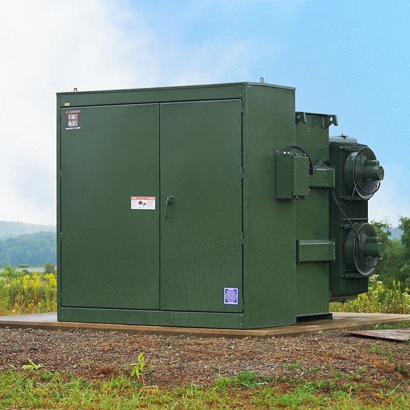
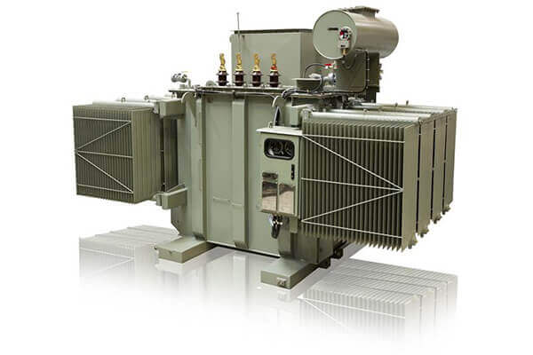
For many industrial and commercial sites, the 200KVA Oil Immersed Transformer provides dependable voltage conversion and consistent energy supply.
Whether used in substations, industrial facilities, or renewable-energy plants, the purpose of transformer technology remains the same: to protect equipment, improve efficiency, and maintain a steady and safe electricity supply.
2.What is the purpose of the transformer?
What is the purpose of the transformer? Simply put, the primary purpose of a transformer is to efficiently change (step up or step down) the voltage of alternating current (AC) electricity while keeping the overall power relatively constant. This voltage conversion is essential because electricity generated at power plants or solar inverters is often at voltages that are either too high for safe use or too low for efficient long-distance transmission.
In traditional power systems, transformers step up voltage for high-voltage transmission lines to minimize energy losses over hundreds of kilometers. Near the point of consumption, they step it down to safer levels (such as 220V/380V or 480V) that homes, factories, and equipment can use without risk of damage or electric shock.
In solar PV systems, the purpose of the transformer becomes even more critical. Solar panels produce DC power, which inverters convert to AC. The transformer then adjusts this AC output to match grid requirements—often stepping it up for efficient connection to the medium-voltage grid or stepping it down for local loads. Without this function, solar energy could not be safely and efficiently integrated into the existing power infrastructure, leading to higher losses, instability, or incompatibility issues.
Ultimately, whether in utility substations, industrial plants, or renewable energy projects, the purpose of the transformer is to enable safe, efficient, and reliable electricity delivery—acting as the silent bridge that makes modern power systems possible.
3.Why Understanding the Purpose of the Transformer Matters in Solar PV Projects
Understanding what is the purpose of the transformer is especially important when designing or selecting equipment for solar photovoltaic (PV) systems. In a typical solar setup, PV panels generate low-voltage DC power that is first converted to AC by the inverter. The transformer then serves its core purpose: stepping up this AC voltage to medium or high levels suitable for grid connection, or stepping it down for on-site consumption in commercial or industrial facilities.
This voltage adjustment is not just about compatibility — it directly impacts system efficiency, safety, and long-term performance. A well-chosen transformer minimizes energy losses during transmission, provides galvanic isolation to protect the inverter and grid from faults, and helps manage the variable output common in solar energy (such as fluctuations due to weather). In utility-scale solar farms, the purpose of the transformer often includes handling bi-directional power flow and harmonic distortion caused by inverters, ensuring stable integration with the national grid.
For project developers and engineers in Singapore and across Asia, clearly knowing the purpose of the transformer helps avoid common pitfalls like undersized units that overheat or incompatible voltage ratings that cause downtime. Ultimately, it ensures your solar investment delivers maximum energy yield, complies with local grid codes, and operates reliably for decades.
4.Why Is Voltage Conversion Necessary?
Electricity consists of two fundamental properties:
- Current – the rate of electrical flow, measured in amps
- Voltage – the force pushing the electrical flow, measured in volts
To simplify, think of electricity like water in a pipe:
- Current is the amount of water flowing
- Voltage is the water pressure
Power plants transmit electricity at extremely high voltages—often exceeding 300,000 volts—to minimize energy loss over long distances. However, this “electrical pressure” is too intense for direct use in homes or commercial buildings. Just like high-pressure water mains need pressure regulators before water enters your home, high-voltage electricity must be transformed to lower voltages.
This is where step-down transformers come into play. They reduce high transmission voltages to safer, usable levels at the point of consumption. These range from:
- Substation transformers used by utilities
- Pad-mounted transformers outside commercial building
- Pole-mounted transformers installed on utility poles
While residential areas typically use single-phase transformers (for 120/240V supply), commercial and industrial facilities often rely on three-phase transformers delivering 208V or 480V power. In this article, we focus on three-phase distribution transformers.
5.How Do Transformers Work?
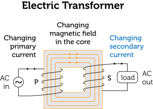
Transformers operate on the principle of electromagnetic induction, a concept first discovered by Michael Faraday. When alternating current flows through the primary winding, it creates a changing magnetic field. This magnetic field then induces a voltage in the secondary winding, allowing electric power to move from one circuit to another without direct electrical contact. This simple but powerful mechanism is what enables transformers work in practice. Whether in a large power transformer or a compact distribution unit, this principle lies at the heart of all transformer design and explains what transformers do at their core.
Instead of producing electricity, a transformer adjusts voltage levels so power can be moved efficiently and safely through the grid. High voltages are essential for long-distance transmission because they reduce energy losses. Once electricity reaches factories, commercial buildings, or homes, the transformer lowers the voltage to levels that equipment and appliances can safely use. This illustrates the essential function of the transformer—and, indeed, the purpose of a transformer: to ensure electricity is delivered at the appropriate voltage for every stage of the power network, enabling both efficient transport and safe end-use.
In practical terms, transformers ensure that power plants, transmission lines, and end-use systems all work together smoothly. By controlling voltage levels and improving energy efficiency, transformers play an essential role in keeping modern electrical infrastructure stable, safe, and reliable.
The Principle of Electromagnetic Induction
Transformers operate on Faraday’s law of electromagnetic induction, which explains how a changing magnetic field can induce voltage in a conductor. This principle enables efficient AC voltage adjustment.
Here’s the basic process:
- Magnetic Field Generation: Alternating current in the primary winding produces a varying magnetic field.
- Magnetic Coupling: The core, typically made of laminated silicon steel, efficiently transfers this field to the secondary winding.
- Voltage Induction: The changing magnetic field induces an AC voltage in the secondary winding. The voltage level depends on the turns ratio of the coils.
The turns ratio determines the voltage transformation:
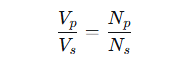
Where:
- Vp = primary voltage
- Vs = secondary voltage
- Np = number of turns in the primary coil
- Ns = number of turns in the secondary coil
A higher turns ratio in the primary coil steps down the voltage, while a higher ratio in the secondary coil steps it up.
Practical Example:
A transformer with a 25:1 turns ratio converts an input of 12,000 V to an output of 480 V. This step-down process enables efficient transmission and safe usage in industrial and commercial applications.
In summary, transformers use electromagnetic induction to enable high-voltage, low-loss power transmission over long distances, followed by safe voltage reduction for practical applications.
6.Transformer Coil Configurations
Transformers achieve voltage conversion through precisely arranged coil systems designed for both efficiency and operational reliability. A basic transformer includes two windings:
- Primary Coil: Draws electrical energy from the input source.
- Secondary Coil: Supplies the converted voltage to the connected load.
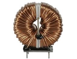
These windings are commonly constructed from copper or aluminum and are wound around a laminated iron core. The core guides magnetic flux to enhance energy transfer between coils while reducing losses. As the core repeatedly magnetizes and demagnetizes with AC current, it undergoes subtle physical vibrations—resulting in the characteristic hum of operating transformers.
Materials and Winding Design
- Copper Windings: Preferred for demanding applications due to superior conductivity, efficiency, and mechanical resilience.
- Aluminum Windings: Offer a balance of performance and economy, suitable where weight and cost are constraints.
- Winding Geometry: Layouts such as layered, disc-type, or helical are selected based on voltage rating, isolation needs, and thermal behavior.
Three-Phase Winding Arrangements
For high-power distribution, three-phase transformers employ specific interconnection strategies to maintain system balance:
- Delta (Δ) Connection: Windings are joined sequentially to form a closed circuit. This setup supports robust performance under high loads, tolerates phase faults, and is widely adopted in industrial settings.
- Wye (Y) Connection: One terminal of each coil connects to a shared neutral, enabling dual voltage outputs (line and phase). This versatility makes it well-suited for distribution grids requiring multiple service voltages.
7.Main Components of a Transformer
While there are many types—such as pad-mounted, pole-mounted, substation, and dry-type transformers—they share common structural elements. Here’s an overview of the major parts found in an oil-filled pad-mounted transformer:
1. Core
The transformer core, made of thin laminated silicon steel sheets, provides a highly effective magnetic path linking the primary and secondary windings. This laminated structure reduces eddy current and hysteresis losses, resulting in smoother magnetic coupling and significantly higher energy transfer efficiency.
2. Coils (Windings)
Within every transformer, precisely wound copper or aluminum conductors form the primary and secondary coils around the iron core. These windings are far more than simple loops of wire—they are meticulously designed to carry substantial electrical currents while offering optimal conductivity, thermal performance, and mechanical resilience.
Connected to the high-voltage input, the primary winding carries alternating current, producing a varying magnetic field within the core.
This magnetic field then intersects the secondary winding, where—through electromagnetic induction—a transformed voltage is generated, tailored to the needs of the load being supplied.
Material selection is critical to transformer performance:
- Copper windings excel in conductivity, mechanical robustness, and resistance to overload, and are often specified for heavy industrial applications.
- Aluminum windings provide a lightweight, economical alternative with sufficient performance for applications where cost efficiency is essential.
Through the synergy of these windings and the magnetic core, transformers achieve high energy efficiency, reduced losses, and extended operational life—qualities that cement their essential role in global power infrastructure.
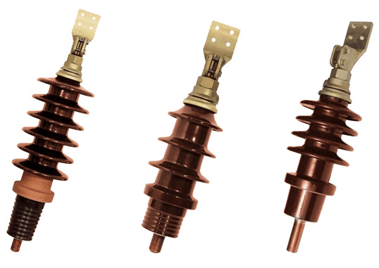
3. Bushings
Insulation bushings are specialized fittings that allow electrical conductors to safely pass through the transformer tank. They provide a fully insulated path, preventing current leakage, safeguarding the internal insulating oil, and maintaining secure connections for both high and low voltage circuits under all operating conditions.
Constructed from durable materials such as porcelain, epoxy resin, or composite polymers, these bushings are designed to endure electrical stress, mechanical forces, and harsh environments, ensuring long-term safety and reliability in power distribution systems.
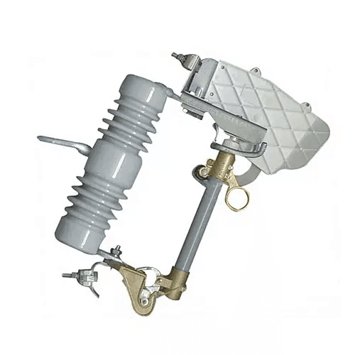
4. Fuses
Fuses serve as essential safety devices within the electrical system. When current rises beyond the designated safe limit, the fuse element automatically melts, breaking the circuit.
This quick interruption protects the transformer and connected equipment from potential overloads, short circuits, and costly damage.
5. Voltage Taps
Voltage taps are access points integrated into a transformer’s primary winding, enabling operators to adjust the number of active turns in the coil. This allows precise regulation of the output voltage to align with grid conditions or load demand. A tap changer—either a manual switch or an automatic on-load mechanism in larger units—facilitates this adjustment.
By utilizing these taps, grid operators and facility managers can effectively respond to input voltage variations, seasonal load shifts, or voltage drops across long distribution lines. This ensures consistent and optimized voltage supply to downstream equipment.
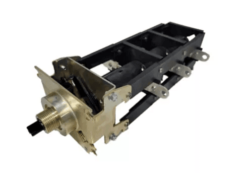
6. Load Break Switch
This device is a rotary load-break switch, designed to safely disconnect the transformer from the live power grid. It enables operators to isolate the equipment even under electrical load, ensuring secure conditions for maintenance, preventing damage to components, and strengthening system-wide protection.
7. Transformer Fluid
Oil-immersed transformers utilize a high-grade insulating oil—either mineral-based or synthetic—that performs two essential roles: thermal management and electrical isolation. As the transformer operates, the oil flows around the active parts, absorbing heat caused by power losses and releasing it through the tank’s radiators or cooling fins. Simultaneously, it acts as a dielectric barrier, preventing arcs and short circuits between energized components.
The oil is contained within a sealed tank system that prevents exposure to humidity and contaminants. Enhanced external cooling surfaces facilitate efficient heat exchange with the ambient air. This integrated oil-based cooling and insulation system supports sustained operation under heavy loads and diverse environmental conditions, contributing to the transformer’s extended lifespan and operational reliability.
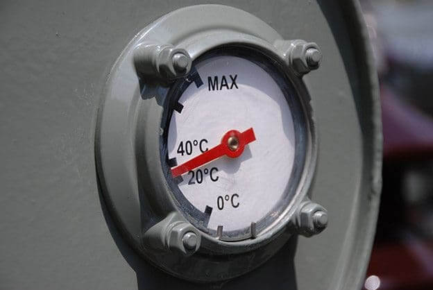
8. Gauges
Gauges are essential for real-time monitoring of transformer operating conditions. Standard instruments measure critical parameters including oil level, temperature, and internal pressure, offering operators early detection of abnormalities such as overheating, leaks, or gas buildup.
In larger or critical installations, these conventional gauges are often enhanced with digital monitoring systems. Equipped with sensors and remote communication features, these advanced systems continuously track performance, trigger alerts during irregularities, and can integrate with smart grid platforms to support predictive maintenance. This proactive approach improves operational safety and reliability while helping to extend the transformer’s service life.
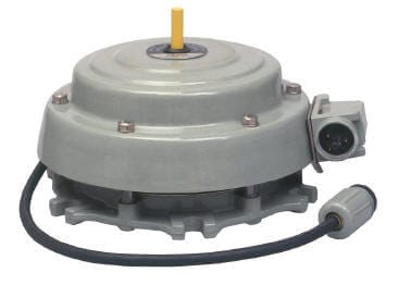
9. Pressure Relief Device
This device functions as a pressure relief valve, engineered to shield the transformer from internal overpressure. In the event of abnormal operating conditions—such as extreme overheating or rapid gas generation—it automatically releases excess pressure in a controlled manner.
This action helps prevent catastrophic tank failure, protects adjacent equipment, and maintains the transformer’s operational safety and integrity.
10. Nameplate
Every transformer features a nameplate that acts as its unique technical identifier. It contains key operational specifications such as kVA rating, input and output voltages, number of phases, winding configuration, frequency, impedance, cooling class, and manufacturer information.
More than just an identification tag, the nameplate offers vital data required for proper installation, system compatibility assessment, and ongoing maintenance. Personnel can use these details to match the transformer with its intended application, prevent operational hazards, and comply with relevant international standards.
8.In Summary
Transformers form the core of today’s electrical systems, enabling the safe and efficient transmission of electric power from generation sites to end users. Although they don’t generate electricity, they play an essential role in adapting electrical energy to suitable voltage levels for a vast range of uses. This is how transformers work: from low-voltage applications like residential electricity and home devices, to medium-voltage supply for commercial facilities, industrial plants, and healthcare centers, all the way to high-voltage requirements for stadium lighting, computing infrastructure, and heavy equipment. Whether in a large power transformer or a distribution unit, the underlying transformer design determines how reliably and effectively electricity flows across the entire network.
The existence of worldwide power grids would be impractical without transformers. They make long-distance transmission feasible through high-voltage operation with reduced losses, and then lower the voltage to levels safe for consumption. In this way, transformers perform as unsung protectors of the electrical network. They operate ceaselessly behind the scenes, shielding delicate devices, improving energy efficiency, and guaranteeing continuous and dependable electricity supply.
For professionals like engineers and energy managers, understanding transformers is practical. It enables energy-efficient designs and reduces operating costs. It also helps build robust power systems. For the public, transformers are unseen daily technology. They power personal electronics and home appliances. They also maintain critical hospital equipment. This all relies on their quiet, reliable performance.
Need help choosing the right transformer for your project?
Contact our team today for expert guidance and tailored solutions.
9.FAQ: Frequently Asked Questions About Transformers
1.What is the purpose of the transformer?
The primary purpose of the transformer is to efficiently change (step up or step down) the voltage of alternating current (AC) electricity while maintaining nearly the same power level. This allows electricity to be transmitted over long distances with minimal energy loss at high voltages, and then safely reduced to usable levels for homes, factories, or equipment. In solar PV systems, the purpose of the transformer is to adjust the AC output from inverters to match grid voltage requirements, ensuring safe and efficient integration of solar energy into the power network.
2.How does a transformer work in a solar PV system?
In a solar PV system, solar panels produce DC power that is converted to AC by the inverter. The transformer then steps up this low-voltage AC to medium or high voltage for grid connection, or steps it down for local loads. It also provides galvanic isolation to protect equipment from faults and helps manage voltage fluctuations caused by changing weather conditions.
3.Why is voltage conversion necessary in power systems?
High voltage minimizes energy losses during long-distance transmission (I²R losses), but it is unsafe and impractical for end-use. Transformers step up voltage at the generation or inverter side and step it down near the point of consumption, balancing efficiency, safety, and compatibility.
4.What are the main components of a transformer?
The key components include the laminated silicon steel core, primary and secondary windings (coils made of copper or aluminum), insulating bushings, transformer oil (for cooling and insulation in oil-immersed types), fuses, voltage taps, gauges, and pressure relief devices. These work together to enable electromagnetic induction and safe voltage transformation.
5.Do solar projects always need a transformer?
It depends on the system scale and voltage requirements. Small rooftop solar systems may not need an additional transformer if the inverter output already matches the grid. However, in commercial, industrial, or utility-scale solar PV projects, a transformer is usually essential for voltage matching, grid compliance, and system protection.
6.What is the difference between step-up and step-down transformers in solar applications?
Step-up transformers increase voltage (commonly used after inverters in solar farms to feed into the medium-voltage grid), while step-down transformers reduce voltage for safe on-site use. Most solar transformers in large PV plants act primarily as step-up units to minimize transmission losses.
7.How to choose the right transformer for a solar PV project?
Consider the inverter output voltage, required grid connection voltage, kVA capacity, cooling method (oil-immersed or dry-type), efficiency rating, and local grid codes (especially important in Singapore and Southeast Asia). Always factor in harmonics handling, bidirectional power flow capability, and environmental conditions.